uEZ GUI Start Here Guide
UEZGUI-1788-43WQR
Rev. 1.11 Aug 31, 2016
Page 3
1.
Hardware Verification
The µEZ GUI kit comes with a pre-installed 4GB or larger SD card that contains files
required for the demo application and slideshow to run. It also contains user manuals,
schematics, and documentation for the product including this guide. FDI recommends
that you visit the documentation tab of the product page of your µEZ GUI to get the
latest documentation.
Power is supplied via the USB power adapter and cable provided in the kit.
1.
Connect the USB cable to the mini USB Type B connector on the µEZ GUI.
2.
Connect the other end of the USB cable to the provided universal AC power
supply’s 5V USB power output.
NOTE: The JTAG port and J-Link probe do not power the µEZ GUI.
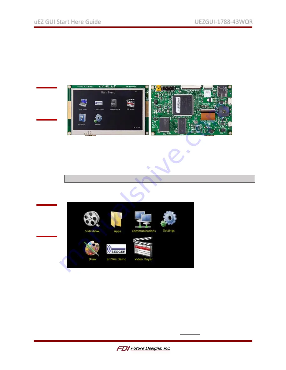
The following screen will appear once power has been connected to the device:
You can now explore the out-of-box demos. Test the GUI by selecting “Draw” and
drawing lines on the screen with your finger.
2.
Software Installation
A.
IDE Installation
All µEZ GUI projects require a development environment to compile and debug the projects.
µEZ currently officially supports IAR Embedded Workbench v7.60 and Rowley CrossWorks
3.6.5 on the LPC1788. This guide uses IAR Embedded Workbench for ARM version 7.60 and
Rowley Crossworks for ARM Version 3.6.5. Download your preferred IDE at the appropriate
Figure 1:
UEZGUI-
1788-
43WQR
Figure 2:
Out-of-Box
(OOB)
Demo


