background image

OPERATION 

ST100A Series Flow Meter 

64 

Fluid Components International LLC 

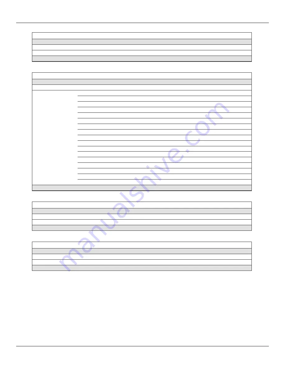
Command 20: Read Long Tag 


Byte 

Format 

Description 

Request Data Bytes 

None 


Response Data Bytes 

0–31 

Latin-1 

Long Tag 

Response Codes 

See 

Table 17

page 

74

, for response code list. 


Command 21: Read Unique Identifier Associated with Long Tag 


Byte 

Format 

Description 

Request Data Bytes 

0–31 

Latin-1 

Long Tag 

Response Data Bytes 

Unsigned-8 

254 


1–2 

Enum 

Expanded Device Type 


Unsigned-8 

Minimum Number Of Preambles From Master to Slave 


Unsigned-8 

HART Protocol Revision Number: 7 


Unsigned-8 

Device Revision Number 


Unsigned-8 

Software Revision Number 


Unsigned-5 

(Most Significant 5 Bits) Hardware Revision Level: 1 


Enum 

Physical Signaling Code: 00 = Bell 202 Current (4-20 mA) 


Bits 

Flags: (Unused) 


9–11 

Unsigned-24 

Device ID 


12 

Unsigned-8 

Minimum Number Of Preambles From Slave to Master 


13 

Unsigned-8 

Maximum Number of Device Variables 


14–15 

Unsigned-16 

Configuration Change Counter 


16 

Bits 

Extended Field Device Status 


17–18 

Enum 

Manufacturer ID Code: 166

DEC

/00A6

HEX

 (FCI) 


19–20 

Enum 

Private Label Distributor Code 


21 

Enum 

Device Profile = 1 “HART Process Automation Device” 

Response Codes 

See 

Table 17

page 

74

, for response code list. 

Command 22: Write Long Tag 


Byte 

Format 

Description 

Request Data Bytes 

0–31 

Latin-1 

Long Tag 

Response Data Bytes 

0–31 

Latin-1 

Long Tag 

Response Codes 

See 

Table 17

page 

74

, for response code list. 

Command 38: Reset Configuration Changed Flag 


Byte 

Format 

Description 

Request Data Bytes 

0–1 

Unsigned-16 

Configuration Change Counter 

Response Data Bytes 

0–1 

Unsigned-16 

Configuration Change Counter 

Response Codes 

See 

Table 17

page 

74

, for response code list. 

Summary of Contents for ST100A Series

Page 1: ......

Page 2: ...tional LLC FCI Disclosure of this data to you is expressly conditioned upon your assent that its use is limited to use within your company only and does not include manufacture or processing uses Any other use is strictly prohibited without the prior written consent of FCI Copyright 2020 by Fluid Components International LLC All rights reserved FCI is a registered trademark of Fluid Components Int...

Page 3: ...t Installation 14 ST100AL In Line Process Connection 16 Flow Transmitter Electronics Installation 16 Instrument Wiring 21 Post Installation Check 33 3 OPERATION 35 Basic Commissioning and Start Up 35 Configuring the ST100A Series 35 Verify Engineering Units 39 System Faults Alarms and Logging Indication 39 ST100A Series Configuration Software Application User Password 2772 40 Real Time Clock 41 To...

Page 4: ...r Service 101 Reference Error Status Register Information 102 APPENDIX A DRAWINGS 105 APPENDIX B ADDITIONAL INFORMATION 135 Parameters Report from the ST100A Series Configuration Software Sample 136 HMI Menu Outline 145 ST100A Series Configuration Software Menu Outline v3 2 0 x 146 Instructions Installing Sun Shield on ST100A Series Integral Enclosure 147 Instructions Installing Sun Shield on ST10...

Page 5: ...0A Series I O Connector Locations 22 Figure 17 ST100A Series Electronics Enclosure Label 23 Figure 18 Bus Configuration 2 mm Jumper Headers and DIP Switch 24 Figure 19 Input Power Wiring 24 Figure 20 ST100A Series Ferrite Core Installation Auxiliary Board Not Shown for Clarity 25 Figure 21 Flow Element Connections TB1 and TB2 Dual Element Models 26 Figure 22 HART and Ch 1 Ch 2 4 20 mA Connections ...

Page 6: ...Deactivation Warning When Enabling HART 53 Figure 56 Field Communicator Easy Upgrade Utility Import DD 55 Figure 57 ST100A Series Configuration Software Output Tab with Modbus Selected 77 Figure 58 ST100A Series Configuration Software Modbus Tab Serial Interface Configuration 78 Figure 59 Extended Operating Mode Status on Front Panel Display EGS Shown 84 Figure 60 Auxiliary Input Configuration 84 ...

Page 7: ...ommand Specific Response Codes 74 Table 18 Command 48 Additional Device Status Bytes Bit Assignments 75 Table 19 HART Engineering Units Codes 76 Table 20 ST100A Series Modbus Function Codes 78 Table 21 ST100A Series Modbus Process Data 79 Table 22 Modbus Service Data Service and Setup Functions 80 Table 23 ST100A Series Modbus Engineering Unit Codes 82 Table 24 ST100A Series Modbus Exception Codes...

Page 8: ...e loss of data or software or minor injury Warning A warning indicates an action that can cause equipment damage or serious injury death or both Caution symbols that may be marked on the product or its packaging are explained below Risk of Danger symbol observe all warnings and cautions in manual Hot Surface Caution symbol risk of burn from probe heater ESD Electrostatic Discharge Susceptibility s...

Page 9: ...from the sensor heater power constant Delta T or the sensor resistance constant power is scaled to drive a 4 20 mA flow output A second temperature output from the unheated reference sensor drives a second 4 20 mA output A third 4 20 mA output is optional Safety Instructions Warning Explosion Hazard Do not disconnect equipment when flammable or combustible atmosphere is present Field wiring shall ...

Page 10: ...perature process output VeriCal option STP100A Single point insertion element with flow temperature and pressure process output STP110A Single point insertion element with flow and temperature process output VeriCal option Documentation and Accessories 06EN003480 ST100A Series Installation Operation Maintenance Manual 06EN003481 ST100A Series Configuration Software Manual Calibration Certification...

Page 11: ... Calibration 0 75 reading 0 5 full scale Temperature 2 F 1 1 C display only flow rate must be greater than 5 SFPS 1 5 m sec Pressure STP Models 0 25 full scale pressure range Response Time Flow 1 second to 63 of final value one step change typical with FP or FPC type flow element operating in AST mode Temperature Coefficient With optional temperature compensation valid from 10 to 100 of full scale...

Page 12: ...tal ferrule or flanged tapped and threaded for fitting ANSI or DIN flanges Compression fittings not available with 850 F 454 C temperature versions of ST100A or ST102AA Retractable Packing Glands Low pressure 50 psig 3 5 bar g or medium pressure 500 psig 34 bar g with graphite or Teflon packing material 1 male NPT or ANSI or DIN flange Teflon packing required when process media is ozone chlorine o...

Page 13: ...r M20 x 1 5 Size 5 W x 5 4 H x 7 75 L 127 mm x 137 mm x 197 mm Local Enclosure Remote Configuration Single cable port enclosure available with packing gland low and med press 1 5 fixed flange fixed NPT process connections NEMA 4X IP66 67 polyester powder coated aluminum or optional 316L stainless steel One 1 cable port 1 11 5 NPT Size 4 68 W x 4 87 H x 5 4 L 119 mm x 124 mm x 137 mm Dual cable por...

Page 14: ...ss steel FCI P N 023241 01 Integral transmitter FCI P N 023237 01 Remote transmitter Ball Valves Cable Glands Certification and Testing Documentation CMTR NACE PMI 02 cleaning radiography dye penetrant hydrostatic or air pressure test certificate of origin certificate of conformance wake frequency strength and more Field Service and Support Start up assistance site commissioning and installation v...

Page 15: ...les accurately FCI recommends 20 nominal pipe diameters upstream and 10 pipe diameters downstream of the instrument installation point for most applications These distances can be significantly reduced when the flow meter is combined with FCI s flow conditioning technology Vortab Insertion flow elements can be mounted into the process using several available customer selectable configurations comp...

Page 16: ...ion fitting installed length 𝐼𝐼 0 50 𝐼𝐼 𝐷𝐷 2 𝑇𝑇 𝐶𝐶 I __________ 2 Mark the insertion pipe at the calculated insertion depth Figure 2 Compression Fitting Installation Dimensions 3 Apply proper thread sealant to the tapered pipe thread on the compression fitting and secure into pipe mounting coupling 4 Insert the flow element to the insertion depth mark making sure the orientation flat is aligned pa...

Page 17: ...ping flat oriented properly Secure flanges with appropriate mounting hardware Figure 3 Example Flange Mount Installation C00991 2 1 REMOTE ENCLOSURE EXPLOSION PROOF AGENCY APPROVED FLANGE SIZE AND RATING CUSTOMER SPECIFIED FLAT TO SHOW FLOW ORIENTATION NPT Pipe Thread Mount The pipe thread configuration is shown in Figure 4 below Apply sealant compatible with the process media to male threads Care...

Page 18: ... centerline Follow the below steps to install retract instruments with the retractable packing gland option as applicable to your configuration also follow the pipe thread or flange mount procedures as described in previous sections Insertion Installation Procedure 1 The scale etched on the side of the insertion probe indicates the length to the tip of the flow element Calculate the insertion dept...

Page 19: ...ace Make sure to move the adjustable nuts at the same time equally to prevent the probe from bending and damaging the packing gland b Tighten the packing nut another to 1 turn tight approximately 65 85 ft lbs 88 115 N m until the packing has created a full seal c Ensure the locking collar is properly secured to the back of the packing gland Torque the two 28 socket head cap screws on the locking c...

Page 20: ...to restrain the retraction be prepared for a rapid pressure impulse of the flow element Check first that there are no objects directly behind the flow element as the insertion probe may retract very quickly 1 Manual Flow Element Retraction Retraction by Hand Pressure 50 psig 3 5 barg max or Using Med Pressure Packing Gland Assembly with Support Rods Pressure 500 psig 35 barg max a Loosen the socke...

Page 21: ...lve If a ball valve is not being used make sure to first depressurize the process line before removing the flow element 2 Flow Element Retraction Using FCI Retractor Tool 026854 01 Pressure 500 psig 35 barg max a Install the FCI retractor tool to the flow element as described in Insertion Installation Procedure page 10 steps a b and c b Loosen the socket head cap screw on the side of the locking c...

Page 22: ...ure transducer will be exposed to the external ambient temperature of the flow element Flow Element Wiring The STP100A can be configured with integral or remote electronics Wiring diagrams for these configurations are located in Appendix A Remote configurations require a 10 conductor shielded cable as specified in Table 2 on page 21 ST102AA and ST112AA Flow Element Installation Models ST102AA and ...

Page 23: ... L C L C L Flow Element Wiring The ST102AA ST112AA can be configured with one integral and one remote flow element or with two separate flow elements and remote electronics Wiring diagrams for these configurations are located in Appendix B Each of the flow elements on the ST102A ST112 are connected to the transmitter using an 8 conductor shielded cable as specified in Table 2 on page 21 ...

Page 24: ...PT MALE NPT OPTIONAL VORTAB 2x FLANGED PROCESS CONNECTION 7x DIA 2x DIA Flow Transmitter Electronics Installation The instrument electronic transmitter can be an integral part of the flow element or it can be mounted remotely using a shielded cable between the flow element and the electronics Use power wiring with a minimum 90 C rating ESD Precautions Caution FCI flow meters contain static sensiti...

Page 25: ... rotating the enclosure to the preferred orientation Do not rotate the electronics enclosure more than 180 degrees Damage to internal wiring may result from over rotating the enclosure Lock Nut Torque Specification 30 35 ft lbs 40 47 N m Provide integral electronics with additional support bracing in applications where excessive vibration is present A mounting bracket is available from FCI to supp...

Page 26: ...ditional mounting details The electronics can be easily mounted on a wall or pipe The mount bracket is designed for 25 inch or M6 mounting hardware Securely mount the electronics to cement or structural support columns or beams Mounting to plaster is not recommended and does not meet system approval requirements Figure 11 Remote Installation Mounting Bracket on Wall C00995 3 1 ST100A SERIES TRANSM...

Page 27: ... the figuresbelow for remote transmitter pipe mounting details Figure 12 Remote Installation Mounting Bracket on 1 1 Pipe Figure 13 Remote Installation Mounting Bracket on 2 Pipe 2 Pipe 2x 3 16 16 U BOLTS SST 2x M4 SCREWS FCI PROVIDED ALUMINUM BRACKET FCI PROVIDED 4x 3 16 HEX NUT ST100A SERIES TRANSMITTER ...

Page 28: ...low Meter 20 Fluid Components International LLC Figure 14 Remote Installation Optional Stainless Steel Bracket on 2 Pipe C01247 2 1 2x M4 SCREWS FCI PROVIDED 2x 20 U BOLTS SST 4x HEX NUT 2 PIPE ST100A SERIES TRANSMITTER 4 25 9 25 ...

Page 29: ...e 2 Interconnecting Cable Minimum Conductor Size Connection Maximum Distance for AWG mm2 10 ft 3 m 50 ft 15 m 100 ft 30 m 250 ft 76 m 500 ft 152 m 1000 ft 305 m Power AC or DC 22 0 3255 22 0 3255 22 0 3255 20 0 5176 18 0 8230 16 1 3087 Flow Element 8 Cond Shielded 24 0 2047 24 0 2047 24 0 2047 22 0 3255 22 0 3255 18 0 8230 STP Flow Element 10 Cond Shielded 22 0 3255 22 0 3255 22 0 3255 22 0 3255 2...

Page 30: ...set screw locking the enclosure body blind lid Then unscrew the blind lid from the enclosure Carefully pull the power and signal wires through the port to avoid damaging the electronics Figure 16 below shows the location of the ST100A Series I O connectors as well as the lid set screw access holes in the enclosure body Note that some of the connectors shown are present only with certain options or...

Page 31: ...to the inside of the blind lid is a label that identifies the ST100A Series jacks and connectors with terminal assignment See Figure 17 below Use this label as a guide when wiring the instrument Note that the PCB silkscreen also provides connector identification Figure 17 ST100A Series Electronics Enclosure Label ...

Page 32: ...NE PULLDOWN LINE PULLUP SIM_ENABLE NV_ERASE HW_LOCK ATION POWER SUPP LY BOARD Under Main Board 1 2 3 1 2 3 1 2 3 ON POSITION ACTIVE WHEN ON LINE CONFIG BUS SELECT J8 FF PROFIBUSADD ON CARD DIAG TEST 1 2 3 Input Power Warning Install an AC line disconnect switch with fuse or breaker between the power source and the flow meter Always disconnect power before performing maintenance on wiring Connect i...

Page 33: ...into the appropriate P1 connector terminals The ferrite core clamp supplied with the instrument as ferrite kit FCI p n 023638 02 protects the instrument against the adverse effects of EMI RFI electrical noise Figure 20 ST100A Series Ferrite Core Installation Auxiliary Board Not Shown for Clarity Power overload protection is provided by a clip mounted SMT fuse Refer to Power Fuse Replacement page 9...

Page 34: ...sor wires to the detachable 9 position connector plug TB2 on the auxiliary board The connector plug accepts 28 16 AWG 0 14 mm2 1 5 mm2 wire refer to Table 2 page 21 for wire size vs length info Connect the flow element cable shield to the connector plug s GND terminal terminal 9 Leave the other end of the shield floating no connection to the flow element enclosure Connect the flow element sensor t...

Page 35: ...n connect external HART to J25 2 EXT HART and external HART to J25 4 EXT HART RTN The block diagram in Figure 23 below shows the single connection and multidrop HART setups Use a 250 Ω 1 0 3 W resistor as shown in the diagram below only if the external HART interface wiring does not have this resistance built in HART requires a minimum loop resistance of 230 Ω Cabling Recommendation Use a shielded...

Page 36: ... connector terminals Refer to Figure 16 and Figure 22 Similar to flow element connector TB1 the J25 connector is a detachable plug that plugs into the header socket on the board The connector plug accepts 28 16 AWG 0 14 mm 2 1 5 mm 2 wire refer to Table 2 page 21 for wire size vs length info Ch 1 is dedicated to HART see HART Connections above for connection details Connect the instrument s second...

Page 37: ...556 VW 1 or equivalent Figure 25 Modbus PROFIBUS Fieldbus Connections J8 C01531 1 1 1 2 3 J12 J13 J10 T1 1 2 3 B FIELDBUS_A RETURN A FIELDBUS_B J25 J21 TB1 1 2 3 J11 J9 MAIN BOARD Modbus PROFIBUS Fieldbus Connector J8 Jumpers J12 J13 set for Modbus configuration positions 1 2 Line Configuration Jumpers J9 J10 J11 see Table in manual POWER SUPP LY BOARD Under Main Board Connect the ST100A Series to...

Page 38: ...Fieldbus PROFIBUS Connections Option Referencing Figure 25 on page 29 connect the FOUNDATION Fieldbus PROFIBUS device network to Phoenix connector J8 on the main board not to be confused with the auxiliary board J8 connector that provides the 3rd 4 20 mA output Note that the FF PROFIBUS connector is also used for the Modbus wiring only one interface can be active at a time Connector J8 accepts 24 ...

Page 39: ...vides a means to activate a simulate mode for Fieldbus conformance testing and for add on card testing diagnostics A particular signal is active when its switch is set to ON For normal use all switches are OFF Source Sink Outputs Pressure Input and External 4 20 mA Input J9 Connections The 6 position terminal strip J9 on the auxiliary board provides connections for the source sink outputs pressure...

Page 40: ...e output power limits listed below Source Output 22 2 VDC output 25 mA maximum supplied by the flow meter Sink Output 40 VDC maximum 150 mA maximum external user supplied power source Figure 29 Source Output J9 Typical External Device Counter etc 24 VDC 25 mA max GND USER WIRING FLOW METER SIDE USER SIDE SOURCE Alternate wiring see note belo w Note Use voltage divider resistor network if flow mete...

Page 41: ...J9 5 Service Port Connection USB Ethernet The instrument s service port provides in depth programming of instrument settings using a PC See Figure 31 below For a simple local service port connection use the USB port Refer to Configuring the ST100A Series page 35 for further information on service port use USB 2 0 USB Type B connector J21 on the main board for local connection of PC to the instrume...

Page 42: ...INSTALLATION ST100A Series Flow Meter 34 Fluid Components International LLC This Page Intentionally Left Blank ...

Page 43: ...ries HMI Front Panel Menu For instruments with the optional HMI display access the instrument s Service menu as described in HMI Option Basics below ST100A Series Configuration Software application The ST100A Series comes with Windows software PC only that provides comprehensive programming of the instrument s settings Refer to ST100A Series Configuration Software page 39 HMI Option Basics The HMI...

Page 44: ...f menus via repeated touches of the left button also exits setup Refer to HMI Menu Outline page 145 for an overall view of the menu structure Note that the front panel menu provides only a small subset of the instrument s settings This makes the front panel menu an ideal tool for quick adjustments Notes The optional HMI interface provides for quick adjustments using only a subset of instrument pro...

Page 45: ...also be changed via the configuration software Refer to Basic Setup Options Configuration Software on page 39 Figure 34 Basic Setup Options HMI INSTRUMENT OPTIONS Figure 35 below summarizes the Instrument options pertaining to the currently selected group of which there are five Enter the HMI user password E C as required when changing a setup parameter Figure 35 Instrument Setup Options Setup Sel...

Page 46: ... When set to Rectangular the width W and height H dimensions are shown set the width and height of the rectanglular pipe in inches The default is Rectangular W 1 0 H 10 0 Table 6 Flow Parameters HMI Flow Type Eng Units Flow Timebase Velocity Std Feet Nml Meters Volumetric Std Cu Feet Per Second Nml Cu Meters Per Minute Nml Liters Per Hour Mass Pounds Per Day Kilograms Metric Tonnes Note Bold type ...

Page 47: ...ut an HMI display use the configuration software to perform basic instrument setup The Basic Setup menu tabs to use are Groups Units Pipe Size and Display Settings If needed use the Alarms and Totalizer tabs to complete the instrument configuration Refer to Basic Setup Options HMI on page 37 for an overview of the setup parameters Refer also to the ST100A Series Configuration Software manual 06EN0...

Page 48: ...ble with a type A male connector on one end and a type B square plug on the other end as supplied with the instrument Connect one end of the USB cable to the computer s USB port Connect the other cable end to the ST100A Series USB port remove blind lid to access USB connector on main board Launch the application by double clicking the configuration software s icon on the PC s Windows desktop An ex...

Page 49: ...icating with the configurator Note also that the HMI presents only a subset of configurable settings Real Time Clock The ST100A Series system time is maintained by a battery powered real time clock that is set to Pacific Time at the factory Synchronize the instrument s system time to the installed location s local time using the configuration software The real time clock cannot be set using the HM...

Page 50: ...e is displayed directly below the indicated flow rate on the instrument display The totalizer is enabled and displayed by default Use the ST100A Series configuration software to set up the totalizer The totalizer cannot be programmed using the HMI menu interface Figure 42 Example Totalizer Display Showing Total Flow Value Start the ST100A Series configuration software application Click USB Connect...

Page 51: ...asic Setup branch from the menu tree on the window s left side Select the SD Card Logging tab Refer to Figure 44 below Configure the tab s Logging section to set up data logging Start Logging Specifies start time of the first log file Choose Start Now immediately or Date Time future Sample Period Specifies how often a log file is generated Period ranges from once every 10 seconds to once every 24 ...

Page 52: ... p m O 2030 E 15 O 2 p m P 2031 F 16 P 3 p m Q 2032 G 17 Q 4 p m R 2033 H 18 R 5 p m S 2034 I 19 S 6 p m T 2035 J 20 T 7 p m U 2036 K 21 U 8 p m V 2037 L 22 V 9 p m W 2038 M 23 W 10 p m X 2039 N 24 X 11 p m Y 2040 O 25 Z 2041 P 26 A 20421 Q 27 R 28 S 29 T 30 U 31 Note 1 After 26 years starting at year 2042 the alphabetical order starts again at A repeating up to 4 times for a 104 year span Table 8...

Page 53: ...Key top sensor for three seconds Select LoggerSDcard Select Inserted This signals the instrument that the microSD card is present and ready to use Secure the electronics enclosure and return the ST100A Series to normal operation Using the ST100A Series Configuration Software Click USB Connect on the welcome screen Select the Basic Setup branch from the menu tree on the window s left side Select th...

Page 54: ... from AST to Constant Power Consult the factory for guidance to determine if the Constant Power mode is optimum for your process conditions Use the configuration software to set the heater mode to AST or Constant Power as follows refer to the ST100A Configuration Software manual 06EN003481 for software details 1 Access the AST Power Mode tab from the Configuration branch of the menu tree See Figur...

Page 55: ...configurator software to adjust the flow damping setting Advanced Setup User Parameters as required for your application Refer to the ST100A Series Configuration Software manual 06EN003481 for details As shown in Figure 47 below an increase in flow damping value results in an output that is increasingly resistant to change amplitude variations Compare the chart s blue curve value 0 25 for 0 flow d...

Page 56: ...car value is 8 readings With readings occurring at 5 times a second the factory boxcar setting is an average of the last 1 6 seconds Caution High boxcar values result in reduced flow response time Make sure that alarm conditions are not affected when using the moving average filter NAMUR Setup German standard NAMUR NE43 defines a fault detection scheme that quickly indicates an instrument fault by...

Page 57: ...o the preselected NAMUR output level Use the Click to Test NAMUR button forces NAMUR output as needed to verify the system setup and wiring Table 9 Fatal Faults that Trigger NAMUR Fault Bit Fatal Fault Error Or Status Descriptions 1 CORE any of these errors I2C error UART error Mutex error or Watchdog Reset 4 CORE unable to update process data PD_NO_FE_DATA Unable to obtain use data from any activ...

Page 58: ...m an HMI initiated idR check is not saved therefore record the data by hand as required Figure 50 Example idR Check Results Display Running the idR Check Using the ST100A Configuration Software Click USB Connect on the home screen Select the Diagnostics branch from the menu tree on the window s left side Select the idR Scheduled Tests tab Select the FE desired from the Selected FE drop down list o...

Page 59: ...strument and Manually Transfer Files with a Card Reader on page 45 Memory Card Log Files The idR log file is always named DLTRLOG which is amended every time a new scheduled test is initiated Process data log files are always a new file with a unique file name seeLog File Naming Convention page 43 The fault log is always named FAULTLOG See Figure 52 below for an example of how these files appear i...

Page 60: ... HOT KEY 1 Normal Operation Display Select and hold the hot key for 3 seconds 2 Select Diagnostics 3 Select Self Test 4 Select FE1 IDR FE 2 applicable to ST100A Series only 5 Input Password E C 6 Select Enter Password 7 Select FE1 IDR again 8 Observe idR test in progress seconds countdown 9 idR Test is Complete Record values for comparison ...

Page 61: ...e displayed now Using Digital Outputs Digital busses includes HART Modbus and FOUNDATION Fieldbus PROFIBUS are mutually exclusive meaning only one can be active at a time When a particular digital output is specified at order time the unit is configured appropriately at the factory Use the ST100A Series configuration software Configuration Output to change the digital output selection Refer to the...

Page 62: ...zer may be turned on or off The process variables include 3 flow classes or types of which only one class of flow is active at a time Table 10 ST100A Series HART Process Variables Slot Process Variable HART Variable Code Description Device Variable Code Device Variable Classification 0 Volumetric Flow1 Primary Variable 0 66 1 Volume Totalizer Secondary Variable 1 68 2 Mass Flow1 Primary Variable 2...

Page 63: ...mmunicator Use the Easy Upgrade Utility from EMERSON to load the DDPs into the Field Communicator Below is the procedure for how to load DD files into the 475 Field communicator Open the Field Communicator Easy Upgrade Utility program and click Utilities on the left hand menu Select Import DDs from a local source Then select the FCI files from the resulting List dialog and click on OK See Figure 5...

Page 64: ...iew and change the engineering units of the process variables review and change the plenum or pipe size enable or disable the Totalizer review and change device information reset the operation of the ST100A Series to the factory settings enable or disable the write protect and PV Setup Process Data Example from Device Setup The Process Data screen lets you review process data including flow rate t...

Page 65: ...e hex values of the Command 48 Additional Device Status 6 byte field bytes 0 5 The topmost Device status shows the value of the More Status Available bit within the HART command response data field b4 in 2nd byte If b4 is set more status is available and the subsequent error s shown in the Additional Device Status bytes Command 48 If b4 is cleared there is no additional status to report Refer to C...

Page 66: ...uid Components International LLC Device Factory Calibration Example from Advance Setup Device Setup The Device Factory Calibration function lets you review the limits that have been set for the Flow Temperature and Pressure process parameters ...

Page 67: ...ommands Command 0 Read Unique Identifier Byte Format Description Request Data Bytes None Response Data Bytes 0 Unsigned 8 254 1 2 Enum Expanded Device Type 3 Unsigned 8 Minimum number of preambles from master to slave 4 Unsigned 8 HART Protocol Revision Number 7 5 Unsigned 8 Device Revision Number 6 Unsigned 8 Software Revision Number 7 Unsigned 5 Most Significant 5 Bits Hardware Revision Level 7 ...

Page 68: ...74 for response code list Command 6 Write Polling Address Byte Format Description Request Data Bytes 0 Unsigned 8 Polling Address of Device 1 Enum Loop Current Mode Response Data Bytes 0 Unsigned 8 Polling Address of Device 1 Enum Loop Current Mode Response Codes See Table 17 for response code list Command 7 Read Loop Configuration Byte Format Description Request Data Bytes None Response Data Byte...

Page 69: ...0 23 Float Slot 2 Device Variable Value 24 Bits Slot 2 Device Variable Status 25 Unsigned 8 Slot 3 Device Variable Code 26 Enum Slot 3 Device Variable Classification 27 Enum Slot 3 Units Code 28 31 Float Slot 3 Device Variable Value 32 Bits Slot 3 Device Variable Status 33 Unsigned 8 Slot 4 Device Variable Code 34 Enum Slot 4 Device Variable Classification 35 Enum Slot 4 Units Code 36 39 Float Slo...

Page 70: ...Manufacturer ID Code 166DEC 00A6HEX FCI 19 20 Enum Private Label Distributor Code 21 Enum Device Profile 1 HART Process Automation Device Response Codes See Table 17 page 74 for response code list Command 12 Read Message Contained Within Device Byte Format Description Request Data Bytes None Response Data Bytes 0 23 Bitstring 24 character message string Response Codes See Table 17 page 74 for resp...

Page 71: ...lue actually used by the field device Command 16 Read Final Assembly Number Byte Format Description Request Data Bytes None Response Data Bytes 0 2 Unsigned 24 STAK ELECT ASSY Response Codes See Table 17 page 74 for response code list Command 17 Write Message Into Device Byte Format Description Request Data Bytes 0 23 Packed Message String Used by Master Response Data Bytes1 0 23 Packed Message St...

Page 72: ...l 202 Current 4 20 mA 8 Bits Flags Unused 9 11 Unsigned 24 Device ID 12 Unsigned 8 Minimum Number Of Preambles From Slave to Master 13 Unsigned 8 Maximum Number of Device Variables 14 15 Unsigned 16 Configuration Change Counter 16 Bits Extended Field Device Status 17 18 Enum Manufacturer ID Code 166DEC 00A6HEX FCI 19 20 Enum Private Label Distributor Code 21 Enum Device Profile 1 HART Process Auto...

Page 73: ...o 0 12 Bits Standardized Status 3 not used bit cleared to 0 13 Bits Analog Channel Fixed 14 24 Bits Device Specific Status2 not used bit cleared to 0 Response Data Bytes 0 5 Bits Device Specific Status only first 6 bytes used see page 75 6 Bits Extended Device Status Normally 0 set to 1 0x01 if maintenance is required 7 Bits Device Operating Mode not used bit cleared to 0 8 Bits Standardized Statu...

Page 74: ...nd Command 42 no data to reset the instrument No response is returned due to reboot Note 1 The value returned in the response data bytes reflects the value actually used by the device Note 1 The value returned in the response data bytes reflects the rounded or truncated value actually used by the device Command 40 Enter Exit Fixed Current Mode Byte Format Description Request Data Bytes1 0 3 Float ...

Page 75: ...ally used by the device Note 1 The value returned in the response data bytes reflects the value actually used by the device Command 50 Read Dynamic Variable Assignments Byte Format Description Request Data Bytes None Response Data Bytes 0 Unsigned 8 Device Variable assigned to the primary variable 1 3 250 Unused Response Codes See Table 17 for response code list Command 51 Write Dynamic Variable A...

Page 76: ...d pressure variables 151 154 157 Group 5 Other Category Commands outside the above listed groups 159 179 180 181 182 183 184 185 186 187 188 191 193 Table 15 below summarizes the instrument s HART Device Specific command set and the data associated with each command Table 15 HART Device Specific Commands Command 137 Read Totalizer And Rollover Values Byte Format Description Request Data Bytes None...

Page 77: ...gned 8 Units Code for Pressure Response Codes See Table 17 page 74 for response code list Command 148 Read Plenum Information Pipe Size Byte Format Description Request Data Bytes None Response Data Bytes 0 3 Float Pipe Height Value 4 7 Float Pipe Width Diameter Value 8 Unsigned 8 Plenum Units Code Response Codes See Table 17 page 74 for response code list Command 149 Write Plenum Information Pipe ...

Page 78: ... Upper Limit Value Response Codes See Table 17 page 74 for response code list Command 159 Write Factory Restore Byte Format Description Request Data Bytes1 None None no data Response Data Bytes None None returns nothing Response Codes See Table 17 page 74 for response code list Command 160 Write 4 20 mA Output Channel 1 Parameters Byte Format Description Request Data Bytes 0 1 Unsigned 16 D A Sett...

Page 79: ...6 D A Setting for 4 mA Out OUTF3 4 Unsigned 8 Channel 3 Out Variable Response Data Bytes 0 1 Unsigned 16 D A Setting for 4 mA Out OUTZ3 2 3 Unsigned 16 D A Setting for 4 mA Out OUTF3 4 Unsigned 8 Channel 3 Out Variable Response Codes See Table 17 page 74 for response code list Command 167 Read 4 20 mA Output Channel 3 Parameters Byte Format Description Request Data Bytes None Response Data Bytes 0...

Page 80: ...ctor2 Byte Format Description Request Data Bytes 0 3 Float Write KFactor2 Response Data Bytes 0 3 Float Write KFactor2 Response Codes See Table 17 page 74 for response code list Command 183 Write KFactor3 Byte Format Description Request Data Bytes 0 3 Float Write KFactor3 Response Data Bytes 0 3 Float Write KFactor3 Response Codes See Table 17 page 74 for response code list Command 184 Write KFact...

Page 81: ...Time Stamp Byte Format Description Request Data Bytes 0 13 Float Read PV value status PV units PV classification code date code and timestamp Response Data Bytes 0 13 Float Read PV value status PV units PV classification code date code and timestamp Response Codes See Table 17 page 74 for response code list HART Command Bit Assignments Command Status Bytes The HART command response data field incl...

Page 82: ...as reached its upper or lower endpoint limit and cannot increase or decease any further Byte 1 3 Loop Current Fixed The loop current is being held at a fixed value and is not responding to process variations Device Status 4 More Status Available More status information is available Refer to Command 48 Additional Device Status Bytes page 75 5 Cold Start A power failure or device reset has occurred ...

Page 83: ...e 4 0 Ethernet Communication Failure Hardware 4 1 USB Communications Failure Hardware 4 2 Industrial Communication Protocol Fail Hardware 4 Byte 2 3 Process Temperature Over Max Limit Hardware 4 4 Process Temperature Under Min Limit Hardware 4 5 Flow Sensor Heater Shorted Hardware 4 6 Not Used 7 Flow Sensor Heater Open Hardware 4 0 Not Used 1 Not Used 2 Flow Sensor A D Counts Under Min Limit Hardw...

Page 84: ...179 Standard Liter per Minute SLPM 190 Standard Cubic Meter per Second SCMS 178 Standard Liter per Hour SLPH 189 Standard Cubic Meter per Minute SCMM 177 Standard Liter per Day SLPD 80 Pounds per Second LBPS 75 Kilograms per Hour KGPH 81 Pounds per Minute LBPM 76 Kilograms per Day KGPD Mass Flow 82 Pounds per Hour LBPH 246 Metric Tonnes Per Second TNPS 83 Pounds per Day LBPD 77 Metric Tonnes Per M...

Page 85: ...etting the ST100A Series for Modbus Operation T100A Series Configuration Software application is used to select the instrument s digital communication protocol Using the supplied USB cable connect the instrument s USB port to a USB port on the PC running the configurator software Launch the ST100A Series Configurator with the PC already connected to the instrument Select Configuration branch from ...

Page 86: ...able 24 page 83 and Table 25 page 83 for Modbus engineering unit codes exception codes and register information respectively ST100A Series Process Data Registers Two data type registers are set up in the ST100A Series to access the process data One uses integer data registers 4000 and the other uses the Daniel extension data registers 5000 All designated registers must be read for each variable va...

Page 87: ...Modbus Slave Register Data Type1 Access Flow Value 5101 Float Read Process Variable Temp Value 5102 Float Read Values Daniel Totalizer Value MS 5103 Float D 2 Read Extension Totalizer Value LS 5104 Float D 2 Read Pressure Value 5105 Float Read Flow MS Value 4101 Special1 Read Flow LS Value 4102 Special1 Read Temperature MS Value 4103 Special1 Read Process Variable Temperature LS Value 4104 Special...

Page 88: ...otalizer Service Register Access using ModScan32 ModScan32 is a Windows based utility by WinTECH Software that lets a PC operate as a Modbus master device for testing Modbus systems Connect the instrument s Modbus terminals to one of the host PC s COM USB port a USB connection will require a USB to RS 485 Serial Adapter Use the utility to access Modbus information as summarized in the following pa...

Page 89: ...mber example Resetting the Totalizer Value Referring to Checking the Totalizer 1 Lower Count Value above repeat step 1 but specify register 4117 instead Length 1 Repeat step 2 above skip if already connected and configured Double click on the register number see pointer in the figure below A pop up Write Register dialog displays Enter the defined hex value 0xABCD in the window s value field and th...

Page 90: ...189 Standard Cubic Meter per Minute SCMM 177 Standard Liter per Day SLPD Mass Flow Modbus Code Unit Description Modbus Code Unit Description 80 Pounds per Second LBPS 75 Kilograms per Hour KGPH 65 Pounds per Minute LBPM 93 Kilograms per Day KGPD 76 Pounds per Hour LBPH 246 Metric Tonnes Per Second MT S 92 Pounds per Day LBPD 77 Metric Tonnes Per Minute MT M 73 Kilograms per Second KGPS 78 Metric T...

Page 91: ...4 16 bit integer Read Totalizer1 LS of float64 value 4105 16 bit integer Read Totalizer2 MS of float64 value 4106 16 bit integer Read Totalizer2 LS of float64 value 4107 16 bit integer Read Pressure MS of float32 value 4108 16 bit integer Read Pressure LS of float32 value 4109 16 bit integer Read Totalizer Modulo MS of float32 value 4110 16 bit integer Read Totalizer Modulo LS of float32 value 411...

Page 92: ... below To use an extended operation mode configure the auxiliary input accordingly See Auxiliary Input Configuration below Note The unit prevents selection of groups whether using optional HMI or configuration software when the instrument is running in an extended mode To select groups again use the configurator to switch the unit back to basic operation Figure 59 Extended Operating Mode Status on...

Page 93: ...Figure 62 Connections for External Flow Input EFI C01423 1 1 1 2 3 4 5 6 1 2 3 4 5 6 2 1 2 1 Aux Board J9 Connector J8 Connector Ch 3 4 20 mA OUT J9 5 4 20 mA IN J9 6 4 20 mA RET Aux Board J8 1 J8 2 ST100A SLAVE UNIT 4 20 mA OUT ST100A MASTER UNIT 4 20 mA IN Start the application Click USB Connect on the home screen Select the Configuration branch from the menu tree on the window s left side Selec...

Page 94: ...nt Observe return to normal operation with Running showing in System Mode field The configurator s Process Data screen will now display EXTENDED OP MODE EFI in the upper left corner see Figure 64 The optional front panel display also shows EFI on the Group Number line after the display is refreshed Refresh the display by cycling the power to the unit or covering the Hot Key HMI option for 3 second...

Page 95: ... as desired to the min 4 mA and max 20 mA input values via the associated Group drop down list Similarly define up to 4 points within the range by entering an input value in the text box and assigning it a calibration group via the associated Group drop down list These entries determine which calibration group is active as the auxiliary input current varies The EGS setup field s Reset button provi...

Page 96: ...OPERATION ST100A Series Flow Meter 88 Fluid Components International LLC Figure 66 Example Process Data Screen with EGS Mode Shown ...

Page 97: ...every 24 months and recalibrating the instrument if required Note that additional regional state or company guidelines may recommend more frequent e g annual verifications or recalibrations FCI recommends periodic cleaning of probes and enclosures Electrical Connections Periodically inspect the wiring for secure connections to the terminal blocks Verify that terminal connections are tight and phys...

Page 98: ...n Power Supply Board a AC Power b DC Power C01425 1 1 SMT Fuse in clip Schurter UMZ 250 2 A 250 VAC Power Connector Opposite Side SMT Fuse in clip Schurter UMZ 250 2 A 125 VDC Power Connector Opposite Side Checking Replacing the Fuse To check the SMT fuse first turn instrument power OFF Replace a fuse with obvious damage e g burnt broken Take a resistance reading across the fuse fuse clip ends See...

Page 99: ...strument connectors and then pull all cable wiring from the cable wiring ports 2 Using a 3 mm hex key remove 2X M4 socket head cap screws securing electronics cage assembly to housing and 1X M4 socket head cap screw securing ground wire to housing Remove electronics card cage assembly from housing 3 Separate bezel HMI sensor assembly from the cage by pulling straight out 4 Remove HMI jumper cable ...

Page 100: ...MAINTENANCE ST100A Series Flow Meter 92 Fluid Components International LLC Figure 68 Instrument Disassembly for Lithium Coin Cell Battery CR2450N Replacement ...

Page 101: ...n Be sure the connectors are firmly mated and the wires are firmly attached to the connector Be sure the wires are inserted between the metal clamps and not between the clamp and plastic connector enclosure Verify correct wiring per wiring diagram in APPENDIX A page 105 Check for Moisture Check for moisture in the enclosures Moisture on the electronics can cause faulty operation If a component of ...

Page 102: ...ature is in degrees Rankine Example General Function Check Tools Needed Digital Multimeter DMM ST100A Series Configuration Software Application USB Cable Type B male to Type A male passive straight through type as supplied with instrument Two Decade Resistance Boxes with resolution from 0 01 to 9999 99 ohms Small size flat blade screwdriver for sensor wiring connection Verifying Setup Connect the ...

Page 103: ...e for a sensor temperature of 70 F 21 C 3 Heater resistance range is 108 120 Ω Note There is added resistance to consider when measuring the flow element from the remote transmitter The cable adds extra resistance The added resistance can be found by measuring the ACT SEN wire to the ACT EXC wire e g TB1 4 to TB1 3 For Remote Units If the measured values do not match that shown in the above table ...

Page 104: ...and reattach the cables when troubleshooting is complete Check the Heater Use the configuration software to check the heater as follows refer to the ST100A Configuration Software manual 06EN003481 for software details 1 Access the Heater Values tab from the Diagnostics branch of the menu tree See Figure 69 below 2 Click Start Data Loop Note that the button changes color when clicked light green to...

Page 105: ...o blink continuous System controller halted hang Cycle the power to see if the instrument recovers from a possible system controller hang Contact FCI Technical Support for assistance if the system status LED is still not blinking Figure 70 System Status LED Main Board Aux Board Not Shown for Clarity After checking the system status LED verify the electronics with the three checks summarized below ...

Page 106: ...branch from the menu tree on the window s left side Select the SIL Adj tab The screen shows power supply voltage readings for 24 VDC and 5 VDC Check that the displayed values are within range as listed in Table 32 below Table 32 Instrument Power Supply Voltages Power Supply Voltage Acceptable Voltage Range Digital 5 VDC 4 75 V to 5 25 V Analog 24 VDC 23 75 V to 24 25 V If the voltage measurements ...

Page 107: ...o the flow meter s calibration Resistance substitution instruments like the FES 200 can be used to check instrument calibration and verify correct operation of the flow transmitter using the Delta R data sheet To verify the transmitter is working properly the sensor head must be disconnected and precision resistance Delta R values from the FES 200 are substituted Then by measuring the transmitter ...

Page 108: ...00 and DMM Reconnect the sensor element connector 10 Close the enclosure making sure none of the wires are strained Ensure any seals and gaskets are properly installed 11 Restore power to the meter If you are troubleshooting the flow meter and the readings are good the flow transmitter is good and the problem may involve the flow element or interconnecting cable If the readings are off a flow elem...

Page 109: ...ue of 12 04 mA is within the allowable limits of 11 98 0 139 mA Example 3 Indicated Display Check using information from above examples Record the indicated display value with FES 200 thumbwheel set to 071 08 156 SCFM indicated on display Determine allowable limits for the 154 8 SCFM table value Note The full scale display value is 310 SCFM in this example Allowable Indicated flow limits 0 0075 x ...

Page 110: ...2 is reporting a fault or an error ST100A Fatal Non Fatal 0x00000002 0 2 to 0 7 FCI Reserved Not Used 0x00000004 to 0x00000080 1 1 to 1 8 FCI Reserved Not Used 0x00000100 to 0x00008000 2 0 PD_FATAL_FAULT At least one FE has a fatal error or fault Fatal 0x00010000 2 1 FCI Reserved Not Used 0x00020000 2 2 PD_NON_OP At least one FE was non operational self test Non Fatal 0x00040000 2 3 PD_SYSTEM_ERRO...

Page 111: ...00800000 3 0 The Reference R ADC converter fails to respond Fatal 0x000001000000 3 1 FCI Reserved Not Used Non Fatal 0x000002000000 3 2 The Reference R ADC s count number is below the minimum Non Fatal 0x000004000000 3 3 FCI Reserved Not Used Non Fatal 0x000008000000 3 4 Process flow is above the maximum limit Non Fatal 0x000010000000 3 5 FCI Reserved Not Used Non Fatal 0x000020000000 3 6 FCI Rese...

Page 112: ...ated Circuit I2C channel 0 bus fails to communicate 0x00008000 2 0 SENSOR_BELOW_MIN_ADC_FAULT The Reference R ADC s count number is below the minimum 0x00010000 2 2 FCI Reserved Not Used 0x00020000 2 2 PORT_EXPANDER_FAULT The port expansion integrated chip fails to respond 0x00040000 2 3 BELOW_dR_MIN_FAULT Delta R value is below minimum limit 0x00080000 2 4 TMP100_ADC_FAULT The ADC for monitoring ...

Page 113: ...iring Diagram Integral ST100A Series 004871 Outline Instl 123 Transmitter ST100 ST100A ST80 Compression Fitting Hazardous Location Integral 004872 Outline Instl 124 Transmitter ST100 ST102A ST100A ST102AA ST80 Compression Fitting Hazardous Location Remote 004852 Outline Instl 125 Transmitter ST100 ST102A ST100A ST102AA ST80 1 inch NPT PGL Hazardous Location Remote 004857 Outline Instl 126 Transmit...

Page 114: ...APPENDIX A DRAWINGS ST100A Series Flow Meter 106 Fluid Components International LLC This Page Intentionally Left Blank ...

Page 115: ...ST100A Series Flow Meter APPENDIX A DRAWINGS Fluid Components International LLC 107 ...

Page 116: ...APPENDIX A DRAWINGS ST100A Series Flow Meter 108 Fluid Components International LLC ...

Page 117: ...ST100A Series Flow Meter APPENDIX A DRAWINGS Fluid Components International LLC 109 ...

Page 118: ...APPENDIX A DRAWINGS ST100A Series Flow Meter 110 Fluid Components International LLC ...

Page 119: ...ST100A Series Flow Meter APPENDIX A DRAWINGS Fluid Components International LLC 111 ...

Page 120: ...APPENDIX A DRAWINGS ST100A Series Flow Meter 112 Fluid Components International LLC ...

Page 121: ...ST100A Series Flow Meter APPENDIX A DRAWINGS Fluid Components International LLC 113 ...

Page 122: ...APPENDIX A DRAWINGS ST100A Series Flow Meter 114 Fluid Components International LLC ...

Page 123: ...ST100A Series Flow Meter APPENDIX A DRAWINGS Fluid Components International LLC 115 ...

Page 124: ...APPENDIX A DRAWINGS ST100A Series Flow Meter 116 Fluid Components International LLC ...

Page 125: ...ST100A Series Flow Meter APPENDIX A DRAWINGS Fluid Components International LLC 117 ...

Page 126: ...APPENDIX A DRAWINGS ST100A Series Flow Meter 118 Fluid Components International LLC ...

Page 127: ...ST100A Series Flow Meter APPENDIX A DRAWINGS Fluid Components International LLC 119 ...

Page 128: ...APPENDIX A DRAWINGS ST100A Series Flow Meter 120 Fluid Components International LLC ...

Page 129: ...ST100A Series Flow Meter APPENDIX A DRAWINGS Fluid Components International LLC 121 ...

Page 130: ...APPENDIX A DRAWINGS ST100A Series Flow Meter 122 Fluid Components International LLC ...

Page 131: ...ST100A Series Flow Meter APPENDIX A DRAWINGS Fluid Components International LLC 123 ...

Page 132: ...APPENDIX A DRAWINGS ST100A Series Flow Meter 124 Fluid Components International LLC ...

Page 133: ...ST100A Series Flow Meter APPENDIX A DRAWINGS Fluid Components International LLC 125 ...

Page 134: ...APPENDIX A DRAWINGS ST100A Series Flow Meter 126 Fluid Components International LLC ...

Page 135: ...ST100A Series Flow Meter APPENDIX A DRAWINGS Fluid Components International LLC 127 ...

Page 136: ...APPENDIX A DRAWINGS ST100A Series Flow Meter 128 Fluid Components International LLC ...

Page 137: ...ST100A Series Flow Meter APPENDIX A DRAWINGS Fluid Components International LLC 129 ...

Page 138: ...APPENDIX A DRAWINGS ST100A Series Flow Meter 130 Fluid Components International LLC ...

Page 139: ...ST100A Series Flow Meter APPENDIX A DRAWINGS Fluid Components International LLC 131 ...

Page 140: ...APPENDIX A DRAWINGS ST100A Series Flow Meter 132 Fluid Components International LLC ...

Page 141: ...ST100A Series Flow Meter APPENDIX A DRAWINGS Fluid Components International LLC 133 ...

Page 142: ...APPENDIX A DRAWINGS ST100A Series Flow Meter 134 Fluid Components International LLC ...

Page 143: ...his appendix contains the following information Parameters Report from the ST100A Series Configuration Software Sample HMI Menu Outline ST100A Series Configuration Software Menu Outline v3 2 0 x Instructions Installing Sun Shield on ST100A Series Integral Enclosure Instructions Installing Sun Shield on ST100A Series Remote Enclosure ...

Page 144: ...APPENDIX B ADDITIONAL INFORMATION ST100A Series Flow Meter 136 Fluid Components International LLC Parameters Report from the ST100A Series Configuration Software Sample ...

Page 145: ...ST100A Series Flow Meter APPENDIX B ADDITIONAL INFORMATION Fluid Components International LLC 137 ...

Page 146: ...APPENDIX B ADDITIONAL INFORMATION ST100A Series Flow Meter 138 Fluid Components International LLC ...

Page 147: ...ST100A Series Flow Meter APPENDIX B ADDITIONAL INFORMATION Fluid Components International LLC 139 ...

Page 148: ...APPENDIX B ADDITIONAL INFORMATION ST100A Series Flow Meter 140 Fluid Components International LLC ...

Page 149: ...ST100A Series Flow Meter APPENDIX B ADDITIONAL INFORMATION Fluid Components International LLC 141 ...

Page 150: ...APPENDIX B ADDITIONAL INFORMATION ST100A Series Flow Meter 142 Fluid Components International LLC ...

Page 151: ...ST100A Series Flow Meter APPENDIX B ADDITIONAL INFORMATION Fluid Components International LLC 143 ...

Page 152: ...APPENDIX B ADDITIONAL INFORMATION ST100A Series Flow Meter 144 Fluid Components International LLC ...

Page 153: ... Raw Signal RefR value dR value TCdR value Temp value Flow value FE2 F2 Raw Signal If present same as above Set up Instrument Group X current active group Flow eng units Temp Deg F or Deg C Pres press units Name group name Restore Pipe Round or Rect W dimension inch H dimension inch Display Orientation select display orientation Contrast select display contrast Language English LoggerSDcard Remove...

Page 154: ...ED SETUP User Parameters Ethernet Date and Time Download Calibration Reboot Device Flow Filtering CONFIGURATION Output 4 20mA User Modbus Extended Operation Mode Group Switch Setup AST Power Mode Auxiliary Input DIAGNOSTICS Status Fault Log idR Scheduled Tasks idR Test Logs Heater Values FACTORY Factory Parameters Identification 4 20mA Factory Options HART Memory Reset idRs SIL Adj FE Faults Core ...

Page 155: ...l Enclosure Step 1 Remove top of sun shield assembly Step 2 Remove existing tag screws Step 3 Attach enclosure to lower portion of sun shield using supplied screws and washers Step 4 Secure tag using supplied hex standoffs Step 5 Reinstall top portion of sun shield using supplied pan head screws and washers Step 6 Finished assembly front and isometric views ...

Page 156: ...p 2 Remove existing tag screws Step 3 Attach enclosure and lower portion of sun shield to remote bracket using supplied screws and washers Choose bracket hole pair that provides best instrument viewing angle in installed location Step 4 Secure tag using supplied hex standoffs Step 5 Reinstall top portion of sun shield using supplied pan head screws and washers Step 6 Finished assembly front and is...

Page 157: ...difference in temperature between the active and reference RTDs Flow Transmitter The portion of the flow meter that conditions converts and scales the flow signal Heater HTR The flow element part that heats the active RTD Local Enclosure The enclosure attached to the flow element usually contains the wiring terminal block Reference Flat A flat part on the sensor head that helps to orient the senso...

Page 158: ...APPENDIX C GLOSSARY ST100A Series Flow Meter 150 Fluid Components International LLC This Page Intentionally Left Blank ...

Page 159: ...ST100A Series Flow Meter APPENDIX D APPROVAL INFORMATION Fluid Components International LLC 151 APPENDIX D APPROVAL INFORMATION EU Information ...

Page 160: ...re T6 T85 C for an ambient temperature range of 40 C to 42 C 40 C to 36 C Electronic Enclosure T5 T100 C for an ambient temperature range of 40 C to 57 C 40 C to 51 C Electronic Enclosure T4 T135 C for an ambient temperature range of 40 C to 65 C 40 C to 60 C For ATEX IECEx Agency Approval system with AST configuration the relationship between the temperature class and process temperature range is...

Page 161: ...x1 5 Gewinde für den Einbau einer nach IEC EN 60079 1 bescheinigten Ex d Kabeleinführung Es ist sicherzustellen dass vor dem Öffnen und bei geöffnetem Deckel des d Gehäuses z B bei Anschluss oder Service Arbeiten entweder die Versorgungsleitung spannungsfrei oder keine explosionsfähige Atmosphäre vorhanden ist Der Deckel des d Gehäuses muss im Betrieb bis zum Anschlag hineingedreht sein Er ist dur...

Page 162: ... ja kannen välissä on räjähdyksen purkausväli Ex d liitäntäkotelossa on 1 2 NPT tai M20x1 5 kierre IEC EN 60079 1 mukaisen Ex d kaapeliläpiviennin asennusta varten Kun d kotelon kansi avataan esim liitännän tai huollon yhteydessä on varmistettava että joko syöttöjohto on jännitteetön tai ympäristössä ei ole räjähtäviä aineita d kotelon kansi on kierrettävä aivan kiinni käytön yhteydessä ja on varm...

Page 163: ...huizing heeft een 1 2 NPT of een M20x1 5 schroefdraad voor aansluiting van een volgens IEC EN 60079 1 goedgekeurde Ex d kabelinvoer De atmosfeer mag niet explosief zijn of de stroomtoevoer moet zijn uitgeschakeld voordat het deksel van de Ex d behuizing wordt geopend bijvoorbeeld bij aansluit of servicewerkzaamheden Het deksel van de d behuizing moet bij normaal bedrijf zijn vastgeschroefd tot aan...

Page 164: ...e de ignición en aplicaciones con baja humedad relativa 30 cuando la superficie pintada está relativamente libre de contaminación en superficie como por ejemplo suciedad polvo o aceite La limpieza de la superficie pintada debe realizarse solo con un paño húmedo 6 No reemplace la batería interna cuando se encuentre en una atmósfera con presencia de gas explosivo S Svenska Säkerhetsanvisningar Säker...

Page 165: ... outside the contiguous United States Alaska or Hawaii contact your country s FCI International Representative or the one nearest to you After Hours Support For product information visit FCI at www fluidcomponents com For product support call 1 800 854 1993 and follow the prerecorded instructions Point of Contact The point of contact for service or return of equipment to FCI is your authorized FCI...

Page 166: ...e call the technician completes a formal detailed service report The formal report is mailed to the customer after the technician s return to the factory or office Field Service Rates All field service calls are billed at the prevailing rates as listed in the FCI Price Book unless previous arrangements have been made with the FCI Customer Service Manager Customers are charged for all travel expens...

Page 167: ...ST100A Series Flow Meter APPENDIX E CUSTOMER SERVICE Fluid Components International LLC 159 ...

Page 168: ...APPENDIX E CUSTOMER SERVICE ST100A Series Flow Meter 160 Fluid Components International LLC ...

Page 169: ...ich they are intended or used Should the Buyer receive defective goods as defined by this paragraph the Buyer shall notify the Seller immediately stating full particulars in support of his claim and should the Seller agree to a return of the goods the Buyer shall follow Seller s packaging and transportation directions explicitly In no case are the goods to be returned without first obtaining a ret...

Page 170: ...ase Haidian District Beijing 100085 P R China Phone 86 10 82782381 Fax 86 10 58851152 Notice of Proprietary Rights This document contains confidential technical data including trade secrets and proprietary information which is the property of Fluid Components International LLC FCI Disclosure of this data to you is expressly conditioned upon your assent that its use is limited to use within your co...

Reviews: