background image

Maintenance - 2000h

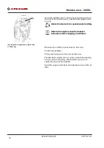
Take great care when draining fluids and oils.

Wear protective gloves and goggles.

Place a receptacle that holds at least 4 liters (1 gal.)

under the drain plug (2).

93

4812274432.pdf

2017-07-10

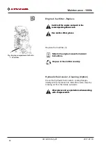
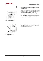
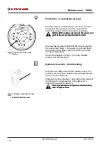
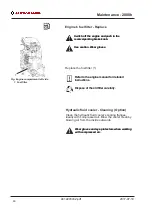
Hydraulic fluid filter - Change

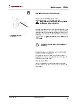
Fig. Engine compartment, left side

     1.  Hydraulic fluid filter

1

Remove the filter (1) and deliver to special waste

handling. This is a single-use filter and cannot be

cleaned.

Remove the filter (1) and deliver to special waste

handling. This is a single-use filter and cannot be

cleaned.

Thoroughly clean the filter holder sealing surface.
Apply a thin coat of fresh hydraulic fluid to the rubber

gasket on the new filter.
Screw the filter on by hand, firstly until the filter gasket

makes contact with the filter base. Then rotate a

further ½ turn.

Do not over-tighten. The seal can be damaged.

Do not over-tighten. The seal can be damaged.

Start the engine and check that the filter does not leak.

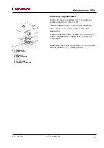
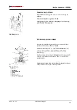
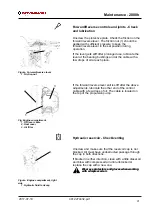
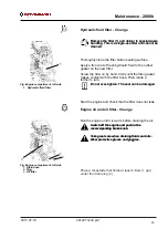
Engine oil and oil filter - Change

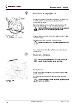
Fig. Engine compartment, left side

     1. Drain hose

     2. Plug

     3. Oil filter

1,

2

3

2

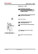
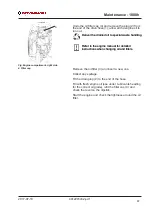
Run the engine until it is warm before draining the oil.

Switch off the engine and push in the

reserve/parking brake knob.

Switch off the engine and push in the

reserve/parking brake knob.

Take great care when draining fluids and oils.

Wear protective gloves and goggles.

Summary of Contents for Dynapac CC900G

Page 1: ...ory roller CC900G CC900G Engine Engine Honda GX630R Honda GX630R Serial number Serial number 10000303x0C003469 0C005137 Translation of original instruction Translation of original instruction Reservation for changes Reservation for changes Printed in China 4812274432 pdf Printed in China 10000303x0C005138 Improved Frame ...

Page 2: ......

Page 3: ...er recommended oils and fluids 9 Higher ambient temperatures above 40 C 104 F 9 Lower ambient temperature Freeze risk 9 Temperatures 9 High pressure cleaning 9 Fire fighting 9 Roll Over Protective Structure ROPS 10 Battery handling 10 Jump starting 11 Technical specifications Noise Vibrations Electrical 13 Vibrations Operator station 13 Noise level 13 Technical specifications Dimensions 15 Dimensi...

Page 4: ... 24 Info decals 25 Instruments Controls 26 Locations Instruments and controls 26 Function description 27 Electrical system 28 Relays and fuses on the machine 28 Operation 29 Before starting 29 Operator s seat Adjusting 29 Sprinkler Check 29 Parking brake 30 Operator position 30 Starting 31 Starting the engine 31 Driving 32 Operating the roller 32 Vibration 33 Manual vibration Switching on 33 Opera...

Page 5: ...paulin 39 Miscellaneous 41 Locking the articulation 41 Lifting the roller 41 Unlocking the articulation 41 Securing CC900G for loading 42 Towing 43 Releasing the brake 43 Towing the roller 45 Operating instructions Summary 47 Preventive maintenance 49 Acceptance and delivery inspection 49 Warranty 49 Maintenance Lubricants and symbols 51 Maintenance symbols 53 Maintenance Maintenance schedule 55 S...

Page 6: ...61 Static drum Filling with water 61 Maintenance 10h 63 Engine Checking the oil level 63 Hydraulic reservoir Level check Filling 63 Refueling 64 Water tank Filling 64 Sprinkler system Check cleaning 64 Air circulation Check 65 Scrapers Check adjustment 65 Warning lamps Check 65 Air cleaner check 66 Maintenance 20h 67 Engine oil and oil filter Change 67 Maintenance 50h 69 Brakes Check 69 Air cleane...

Page 7: ...and joints Check and lubrication 83 Front drum Checking the oil level 84 Hydraulic reservoir Check venting 84 Steering joint Check 85 Air cleaner replace insert 85 Hydraulic fluid filter Change 86 Engine oil and oil filter Change 86 Engine s fuel filter Check 87 Maintenance 2000h 89 Spark plug Replace 89 Engine s fuel filter Replace 90 Forward Reverse controls and joints Check and lubrication 91 H...

Page 8: ...leaner replace insert 92 Hydraulic fluid filter Change 93 Engine oil and oil filter Change 93 Hydraulic reservoir fluid change 95 Front drum Changing the oil 96 Water tank Cleaning 96 4812274432 pdf 2017 07 10 ...

Page 9: ...rocedure that can result in damage to the machine or property if the warning is ignored CAUTION Marks a danger or hazardous procedure that can result in damage to the machine or property if the warning is ignored Safety information The safety manual supplied with the machine must be read by all roller operators Always follow the safety instructions Do not remove the manual from the machine The saf...

Page 10: ...ancer birth defects and other reproductive harm General This manual contains instructions for machine operation and maintenance The machine must be correctly maintained for maximal performance The machine should be kept clean so that any leakages loose bolts and loose connections are discovered at as early a point in time as possible Inspect the machine every day before starting Inspect the entire...

Page 11: ...tches or holes make sure that at least 2 3 of the drum width is on previously compacted material solid surface 9 When driving close to edges ditches or holes make sure that at least 2 3 of the drum width is on previously compacted material solid surface 10 Make sure that there are no obstacles in the direction of travel on the ground in front of or behind the roller or overhead 10 Make sure that t...

Page 12: ...d affect safety Changes are only to be made after written approval has been given by Dynapac 18 Avoid using the roller before the hydraulic fluid has reached its normal working temperature Braking distances can be longer than normal when the fluid is cold See instructions in the STOP section 18 Avoid using the roller before the hydraulic fluid has reached its normal working temperature Braking dis...

Page 13: ...but should then observe caution and operate the machine only when the person is visible or has given clear indications of where he or she is Slopes Fig Operating on slopes Max 20 or 36 This angle has been measured on a hard flat surface with the machine stationary The steering angle was zero the vibration was switched off and all tanks were full Always take into consideration that loose ground ste...

Page 14: ... you steer to the left 6 4812274432 pdf 2017 07 10 Driving near edges Fig Position of drum when driving near an edge 2 3 When driving near an edge minimum 2 3 of the drum width must be on solid ground Keep in mind that the machine s center of gravity moves outwards when steering For example the center of gravity moves to the right when you steer to the left ...

Page 15: ...eat belt is not used there is a great risk that the operator will be thrown off and land under the machine if the machine topples over Always use the seat belt where fitted Where the seat belt is not used there is a great risk that the operator will be thrown off and land under the machine if the machine topples over The seat belt is standard equipment on rollers fitted with Roll Over Protective S...

Page 16: ...Safety when operating 8 4812274432 pdf 2017 07 10 ...

Page 17: ... 122 F the following recommendations apply The petrol engine can be run at this temperature using normal oil However the following fluids must be used for other components Hydraulic system mineral oil Shell Tellus T100 or equivalent Lower ambient temperature Freeze risk Make sure that the watering system is empty drained of water sprinkler hoses tank s or that anti freeze has been added to prevent...

Page 18: ...ith new ROPS structure Never attempt to repair a damaged ROPS structure This must be replaced with new ROPS structure Battery handling When removing batteries always disconnect the negative cable first When removing batteries always disconnect the negative cable first When fitting batteries always connect the positive cable first When fitting batteries always connect the positive cable first Dispo...

Page 19: ...ne Let it run for a while Now try to start the other machine Disconnect the cables in the reverse order 11 4812274432 pdf 2017 07 10 Jump starting Do not connect the negative cable to the negative terminal on the dead battery A spark can ignite the oxy hydrogen gas formed around the battery Do not connect the negative cable to the negative terminal on the dead battery A spark can ignite the oxy hy...

Page 20: ...Special instructions 12 4812274432 pdf 2017 07 10 ...

Page 21: ...s specified in Directive 2002 44 EC Limit is 1 15 m s Measured whole body vibrations are below the action value of 0 5 m s as specified in Directive 2002 44 EC Limit is 1 15 m s Measured hand arm vibrations also were below the action level of 2 5 m s specified in the same directive Limit is 5 m s Measured hand arm vibrations also were below the action level of 2 5 m s specified in the same directi...

Page 22: ...Technical specifications Noise Vibrations Electrical 14 4812274432 pdf 2017 07 10 ...

Page 23: ...lbase 1350 53 1 D Drum diameter 584 23 0 D Drum diameter 584 23 0 H1 Height with ROPS 2300 90 5 H1 Height with ROPS 2300 90 5 H2 Height w o ROPS 1585 62 4 H2 Height w o ROPS 1585 62 4 K1 455 17 9 K1 455 17 9 K2 Ground clearance 261 10 3 K2 Ground clearance 261 10 3 L2 Length 2107 83 0 L2 Length 2107 83 0 S Drum shell thickness 13 0 51 S Drum shell thickness 13 0 51 S A K L H1 H2 D C ...

Page 24: ...ns mm in B Width 970 38 2 B Width 970 38 2 O Overhang 35 1 38 O Overhang 35 1 38 R1 Turning radius outside 2700 106 3 R1 Turning radius outside 2700 106 3 R2 2660 104 7 R2 2660 104 7 W Drum shell thickness 900 35 4 W Drum shell thickness 900 35 4 α Steering angle 34 34 α Steering angle 34 34 O2 O1 α B W R 1 R 2 ...

Page 25: ... 4200 rpm Vibration frequency 70 Hz 4200 rpm Centrifugal force 17 kN 3820 lb Centrifugal force 16 7 kN 3752 lb Note The frequency is measured at high revs The amplitude is measured as the real value and not the nominal Propulsion Propulsion Speed range 0 8 kph 0 5 mph Speed range 0 8 kph 0 5 mph Climbing capacity theoretical 35 Climbing capacity theoretical 35 Compaction data Compaction data s n 0...

Page 26: ...9 M thread 8 8 10 9 12 9 M6 8 4 12 14 6 M6 8 4 12 14 6 M8 21 28 34 M8 21 28 34 M10 40 56 68 M10 40 56 68 M12 70 98 117 M12 70 98 117 M16 169 240 290 M16 169 240 290 M20 330 470 560 M20 330 470 560 M24 570 800 960 M24 570 800 960 M30 1130 1580 1900 M30 1130 1580 1900 M36 1960 2800 M36 1960 2800 Fuses See the Electrical system section fuses General e n i g n E e n i g n E Manufacturer Model Honda GX...

Page 27: ...be dry ROPS bolts which are to be torque tightened must be dry Identification Machine plate 1 Fig Operator s platform left side 1 Machine plate The machine plate 1 is attached to the front left side of the rear frame beside the steering joint The plate specifies the manufacturers name and address the type of machine the PIN Product Identification Number serial number operating weight engine power ...

Page 28: ...ecifications Dimensions Fig PIN Front frame The machine PIN Product Identification Number 1 is punched on the right edge of the front frame 20 4812274432 pdf 2017 07 10 Product identification number on the frame 1 ...

Page 29: ...pdf 2017 07 10 Engine plates The engine serial number 1 is punched below the starter Figure Engine 1 Serial number 2 EPA plate USA 1 2 Please specify the engine serial number when ordering spares Refer also to the engine manual The engine s EPA plate 2 ...

Page 30: ...Machine description Decals 22 4812274432 pdf 2017 07 10 ...

Page 31: ...3424 10 Hoisting plate 4700904870 3 Warning Hot surfaces 4700903424 10 Hoisting plate 4700904870 4 Warning Instruction manual 4700903459 11 Fixing point 4700382751 4 Warning Instruction manual 4700903459 11 Fixing point 4700382751 5 Warning Locking 4700908229 5 Warning Locking 4700908229 6 Handbook compartment 4700903425 6 Handbook compartment 4700903425 7 Petrol fuel 4700381371 7 Petrol fuel 4700...

Page 32: ... Use the part number specified on each decal 4700903422 Warning Crush zone articulation drum Maintain a safe distance from the crush zone Two crush zones on machines fitted with pivotal steering 4700903423 Warning Rotating engine components Keep your hands at a safe distance 4700903424 Warning Hot surfaces in the engine compartment Keep your hands at a safe distance 4700903459 Warning Instruction ...

Page 33: ...s 25 4812274432 pdf 2017 07 10 Info decals Handbook compartment Petrol Lifting point Handbook compartment Petrol Lifting point Hydraulic oil level Hoisting plate Securing point Hydraulic oil level Hoisting plate Securing point ...

Page 34: ...ig Instruments and control panel 1 Ignition key 7 Fuse box 2 Control engine speed 8 Sprinkler 3 Parking brake 4 Vibration on off switch 10 Emergency stop 5 Fuel level hour meter 6 Forward reverse lever 8 3 1 6 2 10 4 11 5 7 11 Choke 2 9 Horn 12 12 Parking brake warning lamp Hydraulic oil termperature not in use 9 ...

Page 35: ... to start the petrol engine The engine cannot be started if the forward reverse lever is in any other position The forward reverse lever controls both the roller s driving direction and speed When the lever is moved forward the roller moves forward etc The roller s speed is proportional to the distance the lever is from the neutral position The further the lever is from the neutral position the hi...

Page 36: ...e restriction relay 12V 10A Fuses Fuses 5 7 5A Start stop valve Fuel pump Restriction relay VBS relay Vibration 5 7 5A Start stop valve Fuel pump Restriction relay VBS relay Vibration 6 15A Horn Backup alarm Fan Option 6 15A Horn Backup alarm Fan Option 28 4812274432 pdf 2017 07 10 Electrical system Relays and fuses on the machine The figure shows the positions of the various fuses and relays The ...

Page 37: ...9 4812274432 pdf 2017 07 10 Operation Before starting Operator s seat Adjusting 1 Fig Operator s seat 1 Length adjustment Adjust the operator s seat so that the position is comfortable and so that the controls are within easy reach The seat can be adjusted lengthways 1 Sprinkler Check Figure Instrument panel 1 Ignition key 3 Parking brake 8 Switch sprinkler 8 3 1 ...

Page 38: ...tion 1 3 2 Fig Operator s station 1 Seat belt 2 ROPS Option 3 Anti slip Replace the seat belt 1 if it shows signs of wear or has been subjected to high levels of force Replace the seat belt 1 if it shows signs of wear or has been subjected to high levels of force Never use the forward reverse levers as a handle when mounting or disembarking from the roller Never use the forward reverse levers as a...

Page 39: ...for too long If the engine does not start immediately wait a minute or so before trying again Do not run the starter motor for too long If the engine does not start immediately wait a minute or so before trying again Warm up the engine at idling speed for a few minutes although longer if ambient temperature is below 10 C 50 F When the engine is warm check that the parking brake warning lamp 12 is ...

Page 40: ...on A hydraulic fluid cooler is recommended for warm ambient temperatures and long operating periods Driving Operating the roller Figure Instrument panel 1 Ignition key 2 Speed control 3 Parking brake 6 Forward Reverse lever 8 Sprinkler knob 10 Emergency stop Under no circumstances is the machine to be operated from the ground The operator must be seated inside the machine during all operation Unde...

Page 41: ...the switch 4 on the underside of the forward reverse lever Always switch off vibration before the roller comes to a standstill 33 4812274432 pdf 2017 07 10 Vibration Manual vibration Switching on Fig Forward Reverse lever 4 Switch vibration On Off Vibration should not be active when the roller is stationary This can damage both the surface and the machine 4 ...

Page 42: ...Operation 34 4812274432 pdf 2017 07 10 ...

Page 43: ... sloping ground Turn the engine speed control 2 back to idling and stop the engine Switch off the machine using the key 1 Activate parking brake knob 3 35 4812274432 pdf 2017 07 10 Operating Stopping Braking Normal braking When starting and driving a machine that is cold remember that the hydraulic fluid is also cold and that braking distances can be longer than normal until the machine reaches th...

Page 44: ...the roller when the lever is moved towards the neutral position A disc brake in each drum motor acts as reserve brake when in motion and as a parking brake when stationary To brake in an emergency situation press in the emergency stop 10 hold the steering wheel firmly and be prepared for a sudden stop Activate the parking brake 3 before leaving the machine Switching off 3 1 10 10 Emergency stop Af...

Page 45: ...ressed Never disembark from the machine when the is engine running unless the reserve parking brake knob is depressed Make sure that the roller is parked in a safe place with respect to other road users Chock the drums if the roller is parked on sloping ground Make sure that the roller is parked in a safe place with respect to other road users Chock the drums if the roller is parked on sloping gro...

Page 46: ...e air cleaner see under the heading Every 50 hours of operation or Every 300 hours of operation or its opening with plastic or tape Also cover the exhaust pipe opening This is to avoid moisture entering the engine Sprinkler system Empty the water tank and all hoses of all water see under the heading Every 2000 hours of operation Fuel tank Fill the fuel tank completely full to prevent condensation ...

Page 47: ...f the forward reverse control bright parts see under the heading Every 500 hours of operation Hoods tarpaulin Lower the instrument cover over the instrument panel Cover the entire roller with a tarpaulin A gap must be left between the tarpaulin and the ground If possible store the roller indoors and ideally in a building where the temperature is constant 39 4812274432 pdf 2017 07 10 ...

Page 48: ...e temperatures and whether the fuel tank is partially or completely filled The air in a partially filled fuel tank promotes fuel deterioration Very warm storage temperatures accelerate fuel deterioration Fuel deterioration problems may occur within a few months or even less if the gasoline was not fresh when you filled the fuel tank Gasoline will oxidize and deteriorate in storage Deteriorated gas...

Page 49: ...he machine s gross weight is specified on the hoisting plate 1 Refer also to the Technical specifications The machine s gross weight is specified on the hoisting plate 1 Refer also to the Technical specifications Lifting gear such as chains steel wires straps and lifting hooks must be dimensioned and used in accordance with the applicable safety regulations for lifting devices Lifting gear such as...

Page 50: ... 2017 07 10 Securing CC900G for loading Securing the CC900G vibratory roller from Dynapac for transport Direct of travel Roller loaded in forward direction 1 2 3 4 double lashings i e one lashing with two parts secured to two different lashing mounts symmetrically located on the right and left sides 1 2 3 4 double lashings i e one lashing with two parts secured to two different lashing mounts symm...

Page 51: ...ble or two single lashings A double lashing runs in a sling through a lashing point or around a machine part and down into two different mounts on the platform Each of lashings 1 3 is either a double or two single lashings A double lashing runs in a sling through a lashing point or around a machine part and down into two different mounts on the platform Lashings in the same direction are placed in...

Page 52: ...he brake piston 107 loose screw approximately 2 turns Tightening the screws 192 too hard can damage the inner mechanism Tightening the screws 192 too hard can damage the inner mechanism The machine should be started with reactivated brake The machine should be started with reactivated brake Restored brake Restored brake Undo the two screws 192 alternately and then insert the plugs 191 Undo the two...

Page 53: ...n towing as the roller has no brakes and can only be slowed and stopped by the vehicle towing the roller The roller must be towed slowly max 3 km h 2 mph and for short distances only max 300 m 1000 ft The roller must be towed slowly max 3 km h 2 mph and for short distances only max 300 m 1000 ft When towing recovering a machine the towing device must be connected to both lifting holes Pulling forc...

Page 54: ...Operating instructions Summary 46 4812274432 pdf 2017 07 10 ...

Page 55: ...ENANCE section are followed 2 Make sure that all instructions in the MAINTENANCE section are followed 3 Set the reserve parking brake to its pulled out position 3 Set the reserve parking brake to its pulled out position 4 Move the forward reverse lever to the NEUTRAL position 4 Move the forward reverse lever to the NEUTRAL position 5 Set the engine speed control to idle 5 Set the engine speed cont...

Page 56: ...Operating instructions Summary 48 4812274432 pdf 2017 07 10 ...

Page 57: ...the customer delivery inspection must be conducted as per the check list in the warranty document Any transport damage must be immediately reported to the transport company Warranty The warranty is only valid if the stiplulated delivery inspection and the separate service inspection have been completed as per the warranty document and when the machine has been registered for starting under the war...

Page 58: ...Preventive maintenance 50 4812274432 pdf 2017 07 10 ...

Page 59: ...c reservoir 12 liters 3 2 gal Hydraulic reservoir 12 liters 3 2 gal Petrol engine 1 5 liters without filter replacement 1 6 qts Petrol engine 1 5 liters without filter replacement 1 6 qts 1 8 liters with filter replacement 1 9 qts 1 8 liters with filter replacement 1 9 qts In climates where there is a risk of freezing see Coolant under the section Lubricants and Symbols Other fuel and lubricants a...

Page 60: ...h biologically degradable fluid The same type of fluid must be used when changing or topping up PANOLIN HLP Synth 46 www panolin com BIOLOGICAL HYDRAULIC FLUID When it leaves the factory the machine may be filled with biologically degradable fluid The same type of fluid must be used when changing or topping up BP Biohyd SE S46 BIOLOGICAL HYDRAULIC FLUID When it leaves the factory the machine may b...

Page 61: ...level Air filter Engine oil filter Battery Engine oil filter Battery Hydraulic reservoir level Sprinkler Hydraulic reservoir level Sprinkler Hydraulic fluid filter Sprinkler water Hydraulic fluid filter Sprinkler water Drum oil level Recycling Drum oil level Recycling Lubricating oil Fuel filter Lubricating oil Fuel filter ...

Page 62: ...Maintenance Lubricants and symbols 54 4812274432 pdf 2017 07 10 ...

Page 63: ...rking brake 9 Sprinkler 15 Steering joint 4 Hydraulic fluid cooler option 10 Scrapers 16 Front drum filling with oil 4 Hydraulic fluid cooler option 10 Scrapers 16 Front drum filling with oil 6 Engine 11 Rubber element 17 ROPS option 6 Engine 11 Rubber element 17 ROPS option 12 Hydraulic fluid filter 18 Static drum filling with water 12 Hydraulic fluid filter 18 Static drum filling with water 55 4...

Page 64: ...omment Pos in fig Action Comment Before starting up for the first time on that day Before starting up for the first time on that day 6 Check the oil level in the engine Refer to the engine manual 6 Check the oil level in the engine Refer to the engine manual 13 Check the hydraulic reservoir level 13 Check the hydraulic reservoir level 14 Refuel 14 Refuel 1 Fill the water tank 1 Fill the water tank...

Page 65: ...tion Comment 3 Test the brakes 3 Test the brakes 7 Clean the air cleaner Refer to the engine manual 7 Clean the air cleaner Refer to the engine manual 11 Check the rubber elements and bolted joints 11 Check the rubber elements and bolted joints Every 100 hours of operation Refer to the contents to find the page number of the sections referred to Pos in fig Action Comment Pos in fig Action Comment ...

Page 66: ...o the engine manual 6 Change the oil filter Refer to the engine manual Check lubrication of controls and pivots Lubricate as necessary Check lubrication of controls and pivots Lubricate as necessary Replace valve cover gasket Refer to the engine manual Replace valve cover gasket Refer to the engine manual Every 500 hours of operation Refer to the contents to find the page number of the sections re...

Page 67: ...cessary Replace valve cover gasket Refer to the engine manual Replace valve cover gasket Refer to the engine manual 6 Clean the combustion chamber Refer to the engine manual 6 Clean the combustion chamber Refer to the engine manual 16 Check the oil level in the front drum 16 Check the oil level in the front drum 13 Check the hydraulic reservoir cover breather 13 Check the hydraulic reservoir cover...

Page 68: ...r Refer to the engine manual 13 Check the hydraulic reservoir cover breather 13 Check the hydraulic reservoir cover breather 15 Check the condition of the articulation 15 Check the condition of the articulation 7 Replace the air cleaner insert Refer to the engine manual 7 Replace the air cleaner insert Refer to the engine manual 12 Change the hydraulic fluid filter 12 Change the hydraulic fluid fi...

Page 69: ...aking adjustments the engine should be switched off and the emergency parking brake should be applied if not otherwise specified 30 Fig static drum 1 Water plug in position for filling 1 Static drum Filling with water Unscrew the filler plug 1 and fill with pure water The recommended volume of water in the drum is 65 liters Where there is a risk of freezing remember to add antifreeze Unscrew the f...

Page 70: ...Maintenance Maintenance measures before use 62 4812274432 pdf 2017 07 10 ...

Page 71: ...ency parking brake should be applied if not otherwise specified Engine Checking the oil level Fig Engine 1 Dipstick 2 Filler plug 1 2 Ensure that the engine cover is fully open when work is carried out under the cover Ensure that the engine cover is fully open when work is carried out under the cover Open the engine cover lock and lower the engine cover forwards Check the oil level using the dipst...

Page 72: ...engine Short circuit press the filler gun against the filler pipe 1 while refuelling Stop the engine Short circuit press the filler gun against the filler pipe 1 while refuelling The tank holds 23 liters 31 7 gal of fuel Water tank Filling Fig Water tank 1 Tank cap 1 Unscrew the tank cap 1 and fill with clean water Unscrew the tank cap 1 and fill with clean water Fill the water tank it holds 175 l...

Page 73: ... Check adjustment Make sure that the scrapers are undamaged Adjust the scrapers if necessary in the following way For firmer application of the scraper undo the locking nut 2 and turn it to the right until the desired application is achieved Lock this setting by tightening the locking nut against the frame side 2 Adjust the pressure on both scraper brackets To set a lower scraper pressure adjust i...

Page 74: ...at hoses and couplings are not leaking and that the air cleaner cover is on properly Clean the air cleaner when operated in extremely dusty environments 66 4812274432 pdf 2017 07 10 Air cleaner check Fig Engine 1 Air filter 1 ...

Page 75: ...rrying out work underneath it Engine oil and oil filter Change Fig Engine compartment left side 1 Drain hose 2 Plug 3 Oil filter 1 2 3 2 Run the engine until it is warm before draining the oil Switch off the engine and push in the reserve parking brake knob Switch off the engine and push in the reserve parking brake knob Take great care when draining fluids and oils Wear protective gloves and gogg...

Page 76: ...nd of the hose Fill with fresh engine oil see under Lubricants heading for the correct oil grade refit the filler cap 4 and check the level on the dipstick Start the engine and check the tightness around the oil filter 68 4812274432 pdf 2017 07 10 ...

Page 77: ...a level surface When checking and making adjustments the engine should be switched off and the emergency parking brake should be applied if not otherwise specified Park the roller on a level surface When checking and making adjustments the engine should be switched off and the emergency parking brake should be applied if not otherwise specified Check that the engine cover is fully open before carr...

Page 78: ...Refit the filter element and the cover and secure the cover with put the latch 1 to locked position Rubber elements and fastening screws Check Figure Drum suspension 1 Rubber element 2 Fastening screws 1 2 Check all the rubber elements 1 and replace all the elements if more than 20 of them on one side of the drum are cracked deeper than 10 15 mm Use a the blade of a knife or pointed object to chec...

Page 79: ...pplied if not otherwise specified Check that the engine cover is fully open before carrying out work underneath it Check that the engine cover is fully open before carrying out work underneath it Spark plug Check and adjustment Fig Engine compartment left side 1 Spark plug 1 Switch off the engine and push in the reserve parking brake knob Switch off the engine and push in the reserve parking brake...

Page 80: ...Maintenance 100h 72 4812274432 pdf 2017 07 10 ...

Page 81: ...not otherwise specified Check that the engine cover is fully open before carrying out work underneath it Check that the engine cover is fully open before carrying out work underneath it Spark plug Replace Fig Engine compartment left side 1 Location of the spark plug on the left and right sides of the engine 1 Switch off the engine and push in the reserve parking brake knob Switch off the engine an...

Page 82: ...Fuel filter 1 Switch off the engine and push in the reserve parking brake knob Switch off the engine and push in the reserve parking brake knob Use caution Wear gloves Use caution Wear gloves Replace the fuel filter 1 Refer to the engine manual for detailed instructions Refer to the engine manual for detailed instructions Dispose of the old filter carefully ...

Page 83: ...the engine until it is warm before draining the oil Switch off the engine and push in the reserve parking brake knob Switch off the engine and push in the reserve parking brake knob Take great care when draining fluids and oils Wear protective gloves and goggles Take great care when draining fluids and oils Wear protective gloves and goggles Place a receptacle that holds at least 4 liters 1 gal un...

Page 84: ...Check and lubrication Figure Forward reverse lever 1 Friction nut 1 Unscrew the protective plate Check the friction on the forward reverse lever The friction nut 1 should be applied with sufficient pressure to keep the forward reverse lever in the set position during operation If the lever gets stiff after prolonged use lubricate the lever at the bearing bushings and at the cable with a few drops ...

Page 85: ...rgency parking brake should be applied if not otherwise specified Park the roller on a level surface When checking and making adjustments the engine should be switched off and the emergency parking brake should be applied if not otherwise specified Check that the engine cover is fully open before carrying out work underneath it Check that the engine cover is fully open before carrying out work und...

Page 86: ... right side 1 Hydraulic fluid tank cap 1 Unscrew and make sure that the reservoir cap is not blocked Air must have unobstructed passage through the cap in both directions If blocked in either direction clean with a little diesel oil and blow with compressed air until unblocked or replace the cap with a new one Wear eye protectors and gloves when working with compressed air Wear eye protectors and ...

Page 87: ...ion and remove the cover 2 Remove the wing nut 3 from the filter element 4 Lift out the foam filter element 8 and the filter element 4 Dry the inside of the filter container and its cover with a damp rag Make sure that dirt does not enter the suction pipe Reinstall with new filter element and secure the cover with put the latch 1 to locked position 79 4812274432 pdf 2017 07 10 Air cleaner replace ...

Page 88: ...Maintenance 500h 80 4812274432 pdf 2017 07 10 ...

Page 89: ...e specified Check that the engine cover is fully open before carrying out work underneath it Check that the engine cover is fully open before carrying out work underneath it Spark plug Replace Fig Engine compartment left side 1 Location of the spark plug on the left and right sides of the engine 1 Switch off the engine and push in the reserve parking brake knob Switch off the engine and push in th...

Page 90: ...r gloves Use caution Wear gloves Replace the fuel filter 1 Refer to the engine manual for detailed instructions Refer to the engine manual for detailed instructions Dispose of the old filter carefully Hydraulic fluid cooler Cleaning Option Clean the hydraulic fluid cooler s cooling flanges ideally with compressed air Blow the cooler clean by blowing air from the inside outwards Wear gloves and eye...

Page 91: ...and lubrication Figure Forward reverse lever 1 Friction nut 1 Unscrew the protective plate Check the friction on the forward reverse lever The friction nut 1 should be applied with sufficient pressure to keep the forward reverse lever in the set position during operation If the lever gets stiff after prolonged use lubricate the lever at the bearing bushings and at the cable with a few drops of oil...

Page 92: ...brake knob Unscrew the plug and check that the oil level reaches the hole s lower edge If necessary top off with fresh transmission fluid See under the heading lubricants for correct fluid grade Clean the magnetic oil plug 1 from any metallic residue and refit the plug Hydraulic reservoir Check venting Figure Engine compartment right side 1 Hydraulic fluid tank cap 1 Unscrew and make sure that the...

Page 93: ...t 8 and the filter element 4 Dry the inside of the filter container and its cover with a damp rag Make sure that dirt does not enter the suction pipe Reinstall with new filter element and secure the cover with put the latch 1 to locked position 85 4812274432 pdf 2017 07 10 Steering joint Check Fig Steering joint Inspect the steering joint to detect any damage or cracks Check and tighten any loose ...

Page 94: ...lder sealing surface Apply a thin coat of fresh hydraulic fluid to the rubber gasket on the new filter Screw the filter on by hand firstly until the filter gasket makes contact with the filter base Then rotate a further turn Do not over tighten The seal can be damaged Do not over tighten The seal can be damaged Start the engine and check that the filter does not leak Engine oil and oil filter Chan...

Page 95: ...al waste handling Refer to the engine manual for detailed instructions when changing oil and filters Refer to the engine manual for detailed instructions when changing oil and filters Remove the oil filter 3 and insert a new one Collect any spillage Fit the drain plug 2 to the end of the hose Fill with fresh engine oil see under Lubricants heading for the correct oil grade refit the filler cap 4 a...

Page 96: ...Maintenance 1000h 88 4812274432 pdf 2017 07 10 ...

Page 97: ...e specified Check that the engine cover is fully open before carrying out work underneath it Check that the engine cover is fully open before carrying out work underneath it Spark plug Replace Fig Engine compartment left side 1 Location of the spark plug on the left and right sides of the engine 1 Switch off the engine and push in the reserve parking brake knob Switch off the engine and push in th...

Page 98: ...r gloves Use caution Wear gloves Replace the fuel filter 1 Refer to the engine manual for detailed instructions Refer to the engine manual for detailed instructions Dispose of the old filter carefully Hydraulic fluid cooler Cleaning Option Clean the hydraulic fluid cooler s cooling flanges ideally with compressed air Blow the cooler clean by blowing air from the inside outwards Wear gloves and eye...

Page 99: ...a few drops of oil at each place 3 2 Fig Engine compartment 1 F R lever cable 2 Heat cover 3 Air filter 1 If the forward reverse lever still is stiff after the above adjustments lubricate the other end of the control cable with a few drops of oil The cable is located on the top of the propulsion pump Hydraulic reservoir Check venting Figure Engine compartment right side 1 Hydraulic fluid tank cap ...

Page 100: ...t 8 and the filter element 4 Dry the inside of the filter container and its cover with a damp rag Make sure that dirt does not enter the suction pipe Reinstall with new filter element and secure the cover with put the latch 1 to locked position 92 4812274432 pdf 2017 07 10 Steering joint Check Fig Steering joint Inspect the steering joint to detect any damage or cracks Check and tighten any loose ...

Page 101: ...lder sealing surface Apply a thin coat of fresh hydraulic fluid to the rubber gasket on the new filter Screw the filter on by hand firstly until the filter gasket makes contact with the filter base Then rotate a further turn Do not over tighten The seal can be damaged Do not over tighten The seal can be damaged Start the engine and check that the filter does not leak Engine oil and oil filter Chan...

Page 102: ...al waste handling Refer to the engine manual for detailed instructions when changing oil and filters Refer to the engine manual for detailed instructions when changing oil and filters Remove the oil filter 3 and insert a new one Collect any spillage Fit the drain plug 2 to the end of the hose Fill with fresh engine oil see under Lubricants heading for the correct oil grade refit the filler cap 4 a...

Page 103: ...servoir fluid change Fig Hydraulic reservoir 1 Draining 1 Use an external drainage pump when draining emptying the hydraulic reservoir Danger of being burned when draining hot oil Wear gloves and eye protectors Danger of being burned when draining hot oil Wear gloves and eye protectors Unscrew the reservoir cap Use an external pump and check that the pump s hose reaches the bottom of the hydraulic...

Page 104: ...wer and push in the reserve parking brake knob Place a receptacle that will hold at least 4 liters 1 gal under the plug Remove the plug 1 and let the oil run out Deliver the drained oil to special waste handling Deliver the drained oil to special waste handling See under the section Every 500 hours of operation for filling oil Water tank Cleaning 1 Fig Water tank 1 Cap Keep in mind that there is a...

Reviews:

Related manuals for Dynapac CC900G