background image

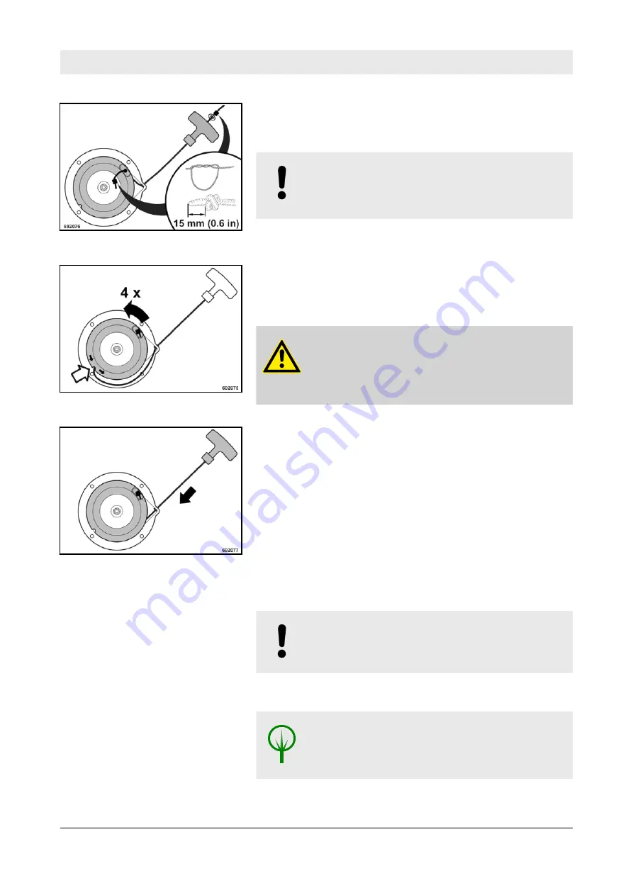
Thread in the new starter rope and fix it with knots on both

ends 

Ä

 Fig.  57.

NOTICE!

Incorrect sense of rotation will damage the spring ends

of the recoil spring.

Pre-tension the coil by approx. 4 rotations in direction of

arrow. Thereby place the starter rope into the recess in the

coil 

Ä

 Fig.  58.

WARNING!
Danger of injury!

Do not let the starter handle hit back, but guide it back

slowly.

Slowly guide the starter handle back to initial position

Ä

 Fig.  59. The rope is thereby wound on the coil.

Test function and light movement of the recoil starter by

pulling the starter handle.

Mount the recoil starter to the engine housing.

6.10.5 

Change the oil in the exciter shaft housing 

NOTICE!

Park the machine on level ground.

For quality and quantity of oil refer to the ”table of fuels and

lubricants”.

ENVIRONMENT!

Catch running out old oil, do not let it seep into the

ground and dispose off environmentally.

Clean the area around breather and drain plug.

Fig.  57

Fig.  58

Fig.  59

Maintenance


BPR 35/42 D - BPR 35/60 D 


68

Go to

Discount-Equipment.com 

to

order your parts

Summary of Contents for BOMAG BPR 35/42 D

Page 1: ...nance Instruction Original Operating Instructions S N 101 692 54 S N 101 692 55 S N 101 692 57 S N 101 692 71 S N 101 692 58 S N 101 692 72 09 2013 Catalogue No 008 083 41 www discount equipment com G...

Page 2: ...e needs We sell worldwide for the brands Genie Terex JLG MultiQuip Mikasa Essick Whiteman Mayco Toro Stone Diamond Products Generac Magnum Airman Haulotte Barreto Power Blanket Nifty Lift Atlas Copco...

Page 3: ...e 54 6 6 2 Check the engine oil level 54 6 6 3 Check the fuel level 55 6 7 Weekly maintenance 57 6 7 1 Check clean the water separator 57 6 8 Maintenance every month 58 6 8 1 Battery serviceOnly machi...

Page 4: ...7 Trouble shooting 75 7 1 General notes 76 7 2 Starting with jump wires 77 7 3 Fuses 78 7 4 Changing the injection pump 79 7 5 Engine problems 84 8 Disposal 87 8 1 Final shut down of machine 88 Table...

Page 5: ...1 Foreword Foreword BPR 35 42 D BPR 35 60 D 5 G o t o D i s c o u n t E q u i p m e n t c o m t o o r d e r y o u r p a r t s...

Page 6: ...if it is used for purposes other than those mentioned in these instructions No warranty claims can be lodged in case of damage resulting from n operating errors n insufficient maintenance and n wrong...

Page 7: ...onditions specified in the general terms of business of BOMAG We wish you successful work with your BOMAG machine BOMAG GmbH Copyright by BOMAG Please fill in Machine type Fig 1 Serial No Fig 1 and 2...

Page 8: ...Fig 2 Fig 3 Foreword BPR 35 42 D BPR 35 60 D 8 G o t o D i s c o u n t E q u i p m e n t c o m t o o r d e r y o u r p a r t s...

Page 9: ...2 Technical data Technical data BPR 35 42 D BPR 35 60 D 9 G o t o D i s c o u n t E q u i p m e n t c o m t o o r d e r y o u r p a r t s...

Page 10: ...496 lbs Basic weight manual starter electric starter 202 222 kg 445 489 lbs Full engine protection cover Optional equipment 18 kg 40 lbs Transport wheels Optional equipment 5 kg 11 lbs Travel characte...

Page 11: ...000 min 1 3000 rpm Drive system mechanical mechanical Exciter system Frequency 80 Hz 4800 vpm Centrifugal force 35 kN 7868 lbf Amplitude 1 5 mm 0 06 in Filling capacities Fuel diesel 3 0 l 0 8 gal us...

Page 12: ...nual starter electric starter 217 237 kg 478 523 lbs Full engine protection cover Optional equipment 18 kg 40 lbs Paving plate Optional equipment 21 kg 46 lbs Transport wheels Optional equipment 5 kg...

Page 13: ...tion data acc to EC Machine Regulation edition 2006 42 EG and the noise regulation 2000 14 EG noise protection guideline 2003 10 EC Vibration Protection Regulation 2002 44 EC were determined during co...

Page 14: ...peration Hand arm vibration Vector total of the weighted effective acceleration in three orthog onal directions Weighted total vibration value BPR 35 42 D ahv 7 3 m s2 on crushed rock determined acc t...

Page 15: ...3 Safety regulations Safety regulations BPR 35 42 D BPR 35 60 D 15 G o t o D i s c o u n t E q u i p m e n t c o m t o o r d e r y o u r p a r t s...

Page 16: ...ndling work Should the recommendations in these instructions be different from the regulations valid in your country you must comply with the safety regulations valid in your country This machine must...

Page 17: ...e the responsibilities must be clearly specified and complied with Persons under the influence of alcohol medicine or drugs are not allowed to operate service or repair the machine Maintenance and rep...

Page 18: ...ly be attached and hoisted by an expert capable person Fasten the lifting gear only at the specified lifting points Check lifting eye for damage before use Do not use a damaged or in any other way imp...

Page 19: ...of fresh air when starting and operating in closed rooms and trenches Operate the machine only with the steering rod folded down Guide the machine only by the steering rod Guide the machine so hat you...

Page 20: ...r and dispose of environmentally Working on electric parts of the machine Before starting to work on electric parts of the machine disconnect the battery and cover it with insulating material Do not u...

Page 21: ...After all maintenance work is completed reinstall all guards and safety installations Repair work must only be performed by qualified and authorized persons Use our repair instructions for this work E...

Page 22: ...cker Lifting point 4 Information sticker Throttle lever 5 Information sticker Travel lever 6 Information sticker Guaranteed sound capacity level 7 Maintenance sticker 8 Brief operating instructions Sa...

Page 23: ...Maintenance sticker Engine Fig 7 Safety regulations BPR 35 42 D BPR 35 60 D 23 G o t o D i s c o u n t E q u i p m e n t c o m t o o r d e r y o u r p a r t s...

Page 24: ...4 Display and control elements Display and control elements BPR 35 42 D BPR 35 60 D 25 G o t o D i s c o u n t E q u i p m e n t c o m t o o r d e r y o u r p a r t s...

Page 25: ...on thoroughly before starting any operation on the machine Here all functions are described in detail The section Operation contains only brief descriptions of the indi vidual control steps Display an...

Page 26: ...il starter n Start switch Only machines with electric starter Position 0 Ignition off warning buzzer off Position I Ignition on warning buzzer on Position II Engine starts warning buzzer off Fig 8 Fig...

Page 27: ...n Operating hour meter Fig 12 Display and control elements BPR 35 42 D BPR 35 60 D 28 G o t o D i s c o u n t E q u i p m e n t c o m t o o r d e r y o u r p a r t s...

Page 28: ...5 Operation Operation BPR 35 42 D BPR 35 60 D 29 G o t o D i s c o u n t E q u i p m e n t c o m t o o r d e r y o u r p a r t s...

Page 29: ...s machine you should thoroughly read chapter Indicators and control elements before starting work All indicators and control elements are described in detail in this chapter Operation BPR 35 42 D BPR...

Page 30: ...manual Park the machine on ground as level as possible Cleaning the machine Check condition of engine and machine fuel tank and fuel lines for leaks screw connections for tight fit For a description o...

Page 31: ...ig 13 and lower the steering rod so that it can swing freely Adjust the steering rod with the height adjustment 1 to the height of your body Fig 13 Operation BPR 35 42 D BPR 35 60 D 32 G o t o D i s c...

Page 32: ...there are no persons in the danger area of engine or machine and that all safety installations are in place Before starting check the starter rope for chafing replace if necessary A damaged rope can...

Page 33: ...starter handle hit back but guide it back If the engine does not start during the first attempt repeat the starting process Set the throttle lever to position MIN Fig 18 Run the engine warm for appro...

Page 34: ...e and that all safety installations are in place Do not use starting aid sprays or other inflammable fluids for starting Always hold on to the machine Always keep an eye on a running machine WARNING L...

Page 35: ...d with a re start lock For a new starting attempt turn the ignition key first back to position 0 Turn the ignition key to position I Fig 21 the warning buzzer sounds Turn the ignition key further to p...

Page 36: ...ed Operation of the vibratory plate can be started as soon as the engine responds to short throttle commands NOTICE When the engine is running leave the ignition key in position I Fig 23 Operation BPR...

Page 37: ...always return the throttle lever to idle speed position this avoids premature wear of the centrifugal clutch Set the throttle lever Fig 24 to position MAX Push the travel lever Fig 25 forward until t...

Page 38: ...he travel lever position Move the travel lever Fig 27 to middle position the machine will vibrate on the spot Keep shifting the throttle lever Fig 28 between MIN and MAX positions At the same time pul...

Page 39: ...engine run with idle speed for a short while Vibration is shut down Set the throttle lever Fig 30 to position STOP On machines with electric starter the warning buzzer will sound Turn the ignition key...

Page 40: ...Engage the locking pawl lever securely Remove the spring cotter Fig 32 and pull the transport wheels out of the bracket on the steering rod Stand at the side of the machine Tilt the machine forward b...

Page 41: ...e base plate and secure it with the spring cotter Unlock the steering rod and fold it down Fig 36 Lock the steering rod in working position Engage the locking pawl lever securely The machine can now b...

Page 42: ...e a damaged or in any other way impaired lifting eye Do not lift or lower the machine jerkily The tension must always be effective in vertical direc tion The machine must not swing about when being li...

Page 43: ...ehicle Lash the vibratory plate down to the transport vehicle so that it is secured against rolling sliding and turning over Fasten the lashing tackle at the marked lashing points Fig 38 Operation BPR...

Page 44: ...6 Maintenance Maintenance BPR 35 42 D BPR 35 60 D 45 G o t o D i s c o u n t E q u i p m e n t c o m t o o r d e r y o u r p a r t s...

Page 45: ...ters in a separate waste container and dispose of environmentally The lifetime of the diesel engine depends to a great extent on the cleanliness of the fuel Keep fuel free of contaminants and water si...

Page 46: ...ne manufacturer Operating errors Incorrect inadequate maintenance If you cannot locate the cause of a fault or rectify it yourself by fol lowing the trouble shooting chart you should contact our custo...

Page 47: ...and ensure strict cleanliness when filling in The fuel provision should always be topped up in due time so that the tank will not run dry The following fuel specifications are permitted n EN 590 n BS...

Page 48: ...35 C 23 F to 95 F SAE 10W 40 5 C to 45 C 23 F to 113 F SAE 10W 40 0 C to 40 C 32 F to 104 F SAE 30 15 C to 30 C 59 F to 86 F SAE 10W 5 C to 5 C 23 F to 41 F SAE 40 20 C to 35 C 68 F to 95 F Fuel Dies...

Page 49: ...l consumption will drop to the normal level after approx 100 to 200 operating hours After 25 operating hours Change the engine oil Check engine and machine for leaks Retighten the fastening screws on...

Page 50: ...enew min every 6 months X 6 8 3 Clean the cooling fins and the cooling air intake openings X 6 9 1 Check the oil level in the exciter housing X 6 9 2 Check the V belt ten sion if necessary replace the...

Page 51: ...as required 6 10 6 Check the hydraulic oil level X 6 10 7 Check the rubber buf fers X 6 11 1 Tighten all bolted con nections X 6 11 2 Engine conservation X Maintenance BPR 35 42 D BPR 35 60 D 53 G o t...

Page 52: ...jet directly into the cooling air openings of the recoil starter into the dry air filter or on electrical equipment Fig 40 After wet cleaning run the engine warm to evaporate all water residues and to...

Page 53: ...do not use open fire do not smoke do not spill any fuel Do not refuel in closed rooms Shut down the engine WARNING Health hazard Do not inhale any fuel fumes NOTICE For quality and quantity of fuel r...

Page 54: ...Fill in fuel through a funnel with screen Close the tank again Fig 42 Maintenance BPR 35 42 D BPR 35 60 D 56 G o t o D i s c o u n t E q u i p m e n t c o m t o o r d e r y o u r p a r t s...

Page 55: ...he water separator depends on the water proportion in the fuel and the care that is execised when refuelling Place the transparent container Fig 43 under the drain plug Loosen the screw for approx 3 t...

Page 56: ...hat the fluid level does not need to be checked Each battery suffers under self discharge which may in not checked occasionally even cause damage to the battery as a result of exhaustive discharge The...

Page 57: ...top up to the filling mark with distilled water Install battery and vibration insulation mats Close the battery box cover again 6 8 2 Check clean the air filter replace if necessary NOTICE Do not use...

Page 58: ...NG Danger of injury Always wear protective clothes goggles gloves when working with compressed air Blow the air filter Fig 46 out from inside to outside with dry compressed air max 5 bar 73 psi Check...

Page 59: ...m all cooling fins and cooling air intake openings and blow it off with compressed air WARNING Fire hazard Do not use any inflammable solvents NOTICE Do not guide the water jet directly into the cooli...

Page 60: ...plug 2 and check the oil level The oil level must reach the bottom edge of the drain bore If the oil level is too low top up oil immediately Clean oil drain and bleeding screw and assemble both screw...

Page 61: ...Reassemble the previously removed spacers Install and fasten the front V belt pulley tightening torque 35 Nm 26 ft lbs Install and fasten the guard tightening torque 15 Nm 11 ft lbs Install the top V...

Page 62: ...et it seep into the ground and dispose off environmentally Screw the oil dipstick out of the oil filler opening Unscrew the oil drain plug and catch running out old oil Fig 52 Clean the oil drain plug...

Page 63: ...housing Fig 53 WARNING Danger of injury Always wear goggles when working with compressed air Blow the engine oil filter out with compressed air from inside to outside Check the seal 1 for damage chan...

Page 64: ...interval to change the fuel filter depends on the cleanliness of the fuel If necessary this service must be performed every six months ENVIRONMENT Catch running out fuel do not let it seep into the g...

Page 65: ...ng the starter rope Unscrew the fastening screws 1 Fig 55 and pull the recoil starter 2 from the engine housing Pull the starter rope with the starter handle 1 out completely Fig 56 Secure the coil 2...

Page 66: ...Fig 59 The rope is thereby wound on the coil Test function and light movement of the recoil starter by pulling the starter handle Mount the recoil starter to the engine housing 6 10 5 Change the oil i...

Page 67: ...y Fill in fresh engine oil through the drain opening Fig 61 Park the machine on level ground Check the oil level The oil level must reach the bottom edge of the drain bore Clean oil drain 2 Fig 62 and...

Page 68: ...od with height adjustment Fig 63 so that the area with the level inspection plugs is horizontal Unscrew the plug Hold the travel lever in forward position Fig 64 Check whether the hydraulic oil level...

Page 69: ...crew Fig 67 Wait until all air has escaped then tighten the bleeding screw Fill in hydraulic oil to approx 40 mm 1 6 in below the edge of the filler opening Fig 68 Filling up hydraulic oil Fig 66 Fig...

Page 70: ...the rubber buffers Check all rubber buffers Fig 70 for tight fit cracks and damage and replace immediately if damaged Fig 69 Fig 70 Maintenance BPR 35 42 D BPR 35 60 D 72 G o t o D i s c o u n t E q u...

Page 71: ...ine oil and fill in anti corrosion engine oil Drain the fuel from the fuel tank mix it well with 10 anti cor rosion oil and fill it in again Instead of mixing anti corrosion oil with the fuel it is al...

Page 72: ...e API MIL classification before taking the machine into service Anti corrosion oils are those that comply with the MIL L 21260 or TL 9150 037 2 resp Nato Code C 640 642 Mark a machine with a conserved...

Page 73: ...7 Trouble shooting Trouble shooting BPR 35 42 D BPR 35 60 D 75 G o t o D i s c o u n t E q u i p m e n t c o m t o o r d e r y o u r p a r t s...

Page 74: ...nsufficient maintenance Whenever a fault occurs you should therefore thoroughly read these instruction on correct oper ation and maintenance If you cannot locate the cause of a fault or rectify it you...

Page 75: ...se the second jump start cable to connect the negative poles on external battery and starter battery Start the engine as described in the chapter Starting the engine When the engine is running remove...

Page 76: ...not use fuses with higher ampere ratings and do not bridge fuses NOTICE Always cover the fuse with the protective cover Fuse 25 A Fig 73 Fig 73 Trouble shooting BPR 35 42 D BPR 35 60 D 78 G o t o D i...

Page 77: ...TICE Ensure strict cleanliness to keep dirt out of the fuel lines Dirt particles can destroy the injection system ENVIRONMENT Catch running out fuel do not let it seep into the ground Remove the air f...

Page 78: ...out fuel Remove the injection nozzles Fig 77 completely with the nozzle base Disassemble the crankcase ventilation grommet Fig 78 Unscrew the oil shut off valve Fig 79 Fig 75 Fig 76 Fig 77 Fig 78 Fig...

Page 79: ...injection pump Unscrew the pressure valve holder 1 Fig 82 with O ring 2 Remove filling piece 3 spring 4 seal ring 5 and pressure valve 6 Fig 80 Fig 81 Fig 82 Trouble shooting BPR 35 42 D BPR 35 60 D...

Page 80: ...ment over the entire control range Replace damaged or worn parts Assemble shim 8 Fig 84 Insert the pump element Fig 85 observe correct posi tioning of the suction hole tapered bore Fig 84 and ele ment...

Page 81: ...k the position of the starting slot to the suction bore visible through the bore the plug is screwed into The starting slot must be arranged centrally to the suction bore or may be maximum one slot wi...

Page 82: ...ses power and speed Fuel tank empty Fill in fuel Throttle lever does not stay in selected position Tighten the nuts Fuel filter clogged Change the fuel filter Tank ventilation blocked Check the tank v...

Page 83: ...he bleeding valve Engine runs with high speed but no vibration Centrifugal clutch defective Change the centrifugal clutch V belt Check tension replace if neces sary Trouble shooting BPR 35 42 D BPR 35...

Page 84: ...8 Disposal Disposal BPR 35 42 D BPR 35 60 D 87 G o t o D i s c o u n t E q u i p m e n t c o m t o o r d e r y o u r p a r t s...

Page 85: ...n tact with skin or clothes Wear protective clothing Remove the batteries and dispose of in compliance with legal regulations ENVIRONMENT Catch all fuels and lubricants do not let them seep into the g...

Page 86: ...e needs We sell worldwide for the brands Genie Terex JLG MultiQuip Mikasa Essick Whiteman Mayco Toro Stone Diamond Products Generac Magnum Airman Haulotte Barreto Power Blanket Nifty Lift Atlas Copco...

Reviews: