Fayat Group BOMAG BW 27 RH-4i Service Manual Download Page 24

1.3

General repair instructions

BOMAG

24

008 922 89


l

Check shaft and bearing housing for discolouration 
or other signs of movement between ball or roller 
bearing and seats.

l

Make sure that shaft and housing are free of burrs 
before assembling the ball or roller bearing.

l

Always mark the individual parts of separable ball or 
roller bearings (e.g. taper roller bearings) to enable 
correct reassembling. Never assemble the rollers to 
an outer race that has already been used, replace 
the complete ball or roller bearing instead.
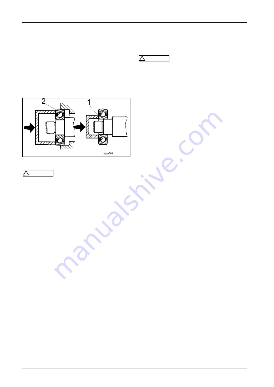
Fig. 7 

!

Caution

When assembling the ball or roller bearing to the 
shaft load must only be applied to the inner race 1 
(Fig. 7).

When fitting the bearing into the housing load 
must only be applied to the outer race (2).

Screws and nuts

Tightening torque

!

Caution

Tighten nuts or screws with the tightening tor-
ques specified in the following tables of tighten-
ing torques. Tightening torques deviating from 
the ones in the table are specially mentioned in 
the repair instructions.

Damaged screws must under no circumstances 
be used any longer. Recutting threads with thread 
cutters or taps adversely affects the strength and 
leak tightness of the screw joint. Damaged or cor-
roded thread pitches can cause incorrect torque 
value readings.

Self-locking nuts must generally be replaced after 
disassembly.

The use of screws with too high strength can 
cause damage!

l

Nut of a higher strength can generally be used in-
stead of nuts of a lower strength classification.

l

When checking or retightening screw joints to the 
specified tightening torque you should first relieve 
by a quarter turn and then tighten to the correct 
torque.

l

Before tightening you should lightly oil the thread, in 
order to ensure low friction movement. 

The same 

applies for self-locking nuts.

l

Make sure that no oil or grease will enter into blind 
tapped bores. The hydraulic power generated when 
turning in the screw could cause breakage of the ef-
fected part.

Summary of Contents for BOMAG BW 27 RH-4i

Page 1: ...Service Manual Catalogue number 008 922 89 09 2014 BW 27 RH 4i S N 101 538 12 S N 861 538 23 S N 861 538 24 S N 861 538 25 Rubber tire roller...

Page 2: ...Find manuals at https best manuals com...

Page 3: ...aulic oil filter B21and B22 60 5 7 Brake oil temperature switch B148 60 5 8 Brake pressure switches B12 and B102 61 5 9 Float switch in water tank B33 62 5 10 Air filter vacuum switch 63 5 11 Descript...

Page 4: ...ant 267 11 13 Check the anti freeze concentration and the condition of the coolant 269 11 14 Clean the cooling fins on engine and hydraulic oil cooler 270 11 15 Check clean the water separator 270 11...

Page 5: ...stem 359 16 1 Overview 360 16 2 Physical basics 362 16 3 Refrigerant R134a 365 16 4 Compressor oil refrigeration oil 366 16 5 Working principle of the air conditioning system 367 16 6 Monitoring devic...

Page 6: ...le 415 18 3 Assembling the front axle 422 Suppliers documentation 445 19 1 Travel pump 447 19 2 Travel motor 489 19 3 Travel gear 543 19 4 Steering valve 617 Circuit diagrams 651 20 1 Hydraulic diagra...

Page 7: ...BOMAG 7 008 922 89 1 General Find manuals at https best manuals com...

Page 8: ...ded for repairs can be taken from the spare parts catalogue for the machine This manual is not subject of an updating service for this reason we would like to draw your attention to our additional Tec...

Page 9: ...fective machine and a machine under re pair by attaching a clearly visible warning label to the dashboard l Block the articulated joint with the articulation lock l Use protective clothes like hard ha...

Page 10: ...ll for an emer gency doctor Operation of high voltage systems i Note The rules and statutory regulations valid in the corre sponding do apply in addition to the notes given here Caution The high volta...

Page 11: ...me distributed by draft Even the smallest por tion of spilled fuel is therefore potentially dangerous l Fire extinguishers charged with FOAM CO2 GAS or POWDER must be available wherever fuel is stored...

Page 12: ...pment of heat may cause the refrigerant to develop toxic and high ly corrosive breakdown products l Pungent smell The toxic substances which are re sponsible for the pungent smell must not be in haled...

Page 13: ...licitly ex cludes any liability for damage caused by the use of non original parts or accessories l Unauthorized changes to the machine are prohibit ed for safety reasons l Do not perform any cleaning...

Page 14: ...s control units you should run a systematic trouble shooting session to eliminate any other possible fault sources Knowledge in basic electrics is re quired for this purpose If a fault was diagnosed w...

Page 15: ...ll control units in order to protect the electrical sys tem of the machine l Disconnect the minus pole of the battery or interrupt the electric circuit with the main battery switch l Isolate the gener...

Page 16: ...id charging of the battery or electric welding on the vehicle When cleaning the generator with a steam or water jet make sure not to direct the steam or water jet directly on or into the generator ope...

Page 17: ...ause l Before taking new hydraulic components into oper ation fill these with hydraulic oil as specified in the operating and maintenance instructions l After changing a hydraulic component thoroughly...

Page 18: ...void that damp air is drawn into the component by the differ ence in temperatures l Damaged or leaking parts of the air conditioning must not be repaired by welding or soldering but must generally be...

Page 19: ...commissioning mainte nance and repair work particularly for engines with the Common Rail System Contamination like dirt welding residues or similar can lead to the failure of in dividual components a...

Page 20: ...of extraction Vacuum cleaning equipment must generally be used for cleaning when the fuel system is open l Working means and tools must be cleaned before being used for work Use only tools without da...

Page 21: ...fore being used for work Use only tools without dam aged chromium coating or tools without chromium coating Fuel hoses Fig 2 Caution All fuel hoses have two layers of material a rein forced rubber coa...

Page 22: ...compressed air replace any O rings and seals that have been dis lodged by the compressed air Assembly of radial seals Fig 3 l Lubricate the sealing lips 2 Fig 3 with clean grease in case of double sea...

Page 23: ...ced l Remove any lubricant residues from the ball or roll er bearing to be examined by washing it with gaso line or any other appropriate degreasing agent Ensure strict cleanliness l Check balls or ro...

Page 24: ...ghten ing torques Tightening torques deviating from the ones in the table are specially mentioned in the repair instructions Damaged screws must under no circumstances be used any longer Recutting thr...

Page 25: ...h The corresponding calculation requires a higher effort and in the end depends on the materials to be bolted together Strength classes of metric nuts Nuts are differentiated by three load groups Each...

Page 26: ...tion is identified by a dot or the manufacturer s symbol l The strength class is identified by a dash b Identification of UNF threads Fig 11 Screws The screw head is marked with a stamped in round cav...

Page 27: ...8 922 89 1 3 Cotter pins Fig 12 In places where cotter pins are used these must be reassembled Cotter pins must generally be renewed after disassembly Cotter pins must be assembled as shown in the ill...

Page 28: ...ad Coefficient of friction tot 0 14 Screw dimension Tightening torques Nm 8 8 10 9 12 9 M4 3 5 5 M5 6 9 10 M6 10 15 18 M8 25 35 45 M10 50 75 83 M12 88 123 147 M14 137 196 235 M16 211 300 358 M18 290 4...

Page 29: ...287 M16 x 1 5 180 255 307 M18 232 330 392 M18 x 1 5 260 373 444 M20 330 463 557 M20 x 1 5 369 502 620 M22 448 628 754 M22 x 1 5 495 691 847 M24 569 800 960 M24 x 2 624 879 1036 M27 840 1184 1520 M27...

Page 30: ...htening torques for screws with UNC thread UNC Unified Coarse Thread Series American Unified Coarse Thread Coefficient of friction tot 0 14 Screw dimension Tightening torques Nm 8 8 10 9 12 9 1 4 20 1...

Page 31: ...0 2300 1 1 4 12 1900 2700 3200 1 3 8 12 2600 3700 4400 1 1 2 12 3300 4600 5600 Coefficient of friction tot 0 14 Tightening torques for screws with UNF thread UNF Unified National Fine Thread Series Am...

Page 32: ...1 4 Tightening torques BOMAG 32 008 922 89...

Page 33: ...BOMAG 33 008 922 89 2 Pneumatic tires rollers...

Page 34: ...nsitive travel control This is very import for the realization of jerk free reversing How ever new trends have also been set with respect to safety e g by the dynamic service brakes These are maintena...

Page 35: ...d with sand or scrap steel for flexible weight adjustment The version with water tight welded frame option can also be filled with water The correct contact pressure Fig 14 Tire pressure The success o...

Page 36: ...2 1 Rubber tire roller BOMAG 36 008 922 89 Fig 15 Even weight distribution to each individual wheel Tipping resistant design with level compensation...

Page 37: ...BOMAG 37 008 922 89 3 Technical data...

Page 38: ...h 0 6 5 mph Travel speed 3 0 20 km h 0 12 4 mph Max gradability 27 27 Drive Engine manufacturer Deutz Deutz Type TCD 4 1 L4 TCD 4 1 L4 Exhaust classification Europe 97 68 EU Stage 3B Stage 3B Exhaust...

Page 39: ...High idle speed rpm 2200 Spec Fuel consumption g kWh 212 Valve clearance intake 75 15 Valve clearance exhaust 120 15 Travel pump Manufacturer Bosch Rexroth Type A4VG 105 DA System Axial piston swash...

Page 40: ...e in mm 2 1 Weight of machine kg lb Wheel load kg lb Tire pressure bar psi 3 44 4 58 5 73 6 87 7 102 8 116 10400 22928 1300 2866 3 2 45 3 4 48 3 6 52 3 9 55 4 2 60 4 5 64 12000 26455 1500 3307 3 4 84...

Page 41: ...This as a preview PDF file from best manuals com Download full PDF manual at best manuals com...

Reviews: