


Specifications subject to change without notice
Description of function of inputs and outputs
8.2.3. Supervision signal Ready / Error (21)
The ready-signal is to show the status of the drive and can be used to provide a feedback
signal to other devices and controls. The open-collector output is normally turned off
which means the output is pulled to a positive level by an external connected resistor,
if there is no fault within the drive system.
In the case of a fault like under voltage, overvoltage, overheat or overcurrent the internal
transistor is on, the output is pulled to GND.
Input range max. 30 VDC
load current < 20 mA
any fault is stored and can be reset by enable off and on.
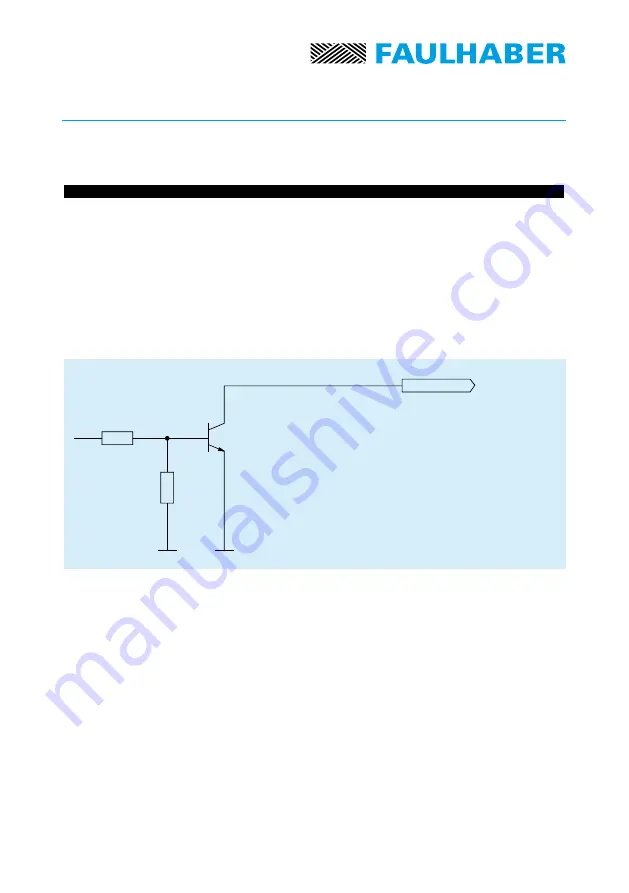
Output circuit ready/error signal:
8.2.4. Motor C (3)
8.2.5. Motor B (2)
8.2.6. Motor A (1)
motor connection.
8.2.7. + 5 V, 100 mA (6)
auxiliary voltage source for power supply of hallsensors and/or incremental encoder
8.2.8. + 15 V 20 mA (14)
8.2.9. – 15 V 20 mA (16)
auxiliary voltage source for use as reference voltages by setting the set value by the means
of an external potentiometer
ERROR
12


