Faulhaber 2232 BX4 IMC Technical Manual Download Page 10

1st edition, 9.04.2024

7000.05073, 1st edition, 9.04.2024

7000.05073

Safety

10

2.2.3

Heat development

Active components may cause the MCS to heat up. If touched, there is a risk of burning.

Protect the MCS against being touched and cool sufficiently.

If necessary, affix a suitable warning sign in the immediate vicinity of the MCS.
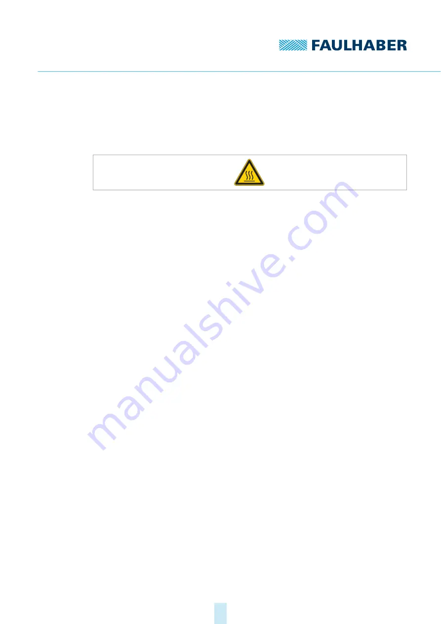
Fig. 1:

Suitable warning sign acc. to DIN EN ISO 7010

2.3

Environmental conditions

Select the installation location so that clean dry air is available for cooling the MCS.

Select the installation location so that the air has unobstructed access to flow around 
the MCS.

When installed within housings and cabinets take particular care to ensure adequate 
cooling of the MCS.

Select a power supply that is within the defined tolerance range.

Protect the MCS against heavy deposits of dust, in particular metal dust and chemical 
pollutants.

Protect the MCS against humidity and wet.

Summary of Contents for 2232 BX4 IMC

Page 1: ...WE CREATE MOTION Technical Manual Motion Control System MCS 2232 BX4 IMC 2250 BX4 IMC EN...

Page 2: ...aber GmbH Co KG cannot accept any liability for any errors in this document or for the consequences of such errors Equally no liability can be accepted for direct or consequential damages resulting fr...

Page 3: ...llation 14 4 1 Mounting 14 4 1 1 Mounting instructions 14 4 1 2 Mounting the motor 15 4 2 Electrical connection 16 4 2 1 Notes on the electrical connection 16 4 2 2 Electrical connection of motor 17 4...

Page 4: ...dition 9 04 2024 7000 05073 1st edition 9 04 20247000 05073 Content 4 7 Warranty 36 8 Additional documents 37 8 1 Declaration of Conformity 22xx BX4 IMC 37 8 2 Declaration of Incorporation 22xx BX4 IM...

Page 5: ...onal information from the following manuals is useful These manuals can be downloaded in pdf format from the web page www faulhaber com manuals 1 3 Using this document Read the document carefully befo...

Page 6: ...gh CAN_L CAN Low CO CANopen interface acc to CiA 402 DigIn Digital input DigOut Digital output EFS Electronics Filter Supply EMC Electromagnetic compatibility ESD Electrostatic discharge GND Ground IM...

Page 7: ...avoided death or serious injury may result Measures for avoidance CAUTION Danger with low level of risk if not avoided minor or moderate injury may result Measures for avoidance NOTICE Risk of damage...

Page 8: ...led in accordance with the ESD regulations Do not use the Motion Control Systems in environments where it will come into contact with chemicals nor in explosion hazard areas The Motion Control Systems...

Page 9: ...d by an electrician During all work on the electrical equipment observe the 5 safety rules a Disconnect from power b Secure against being switched on again c Check that no voltage is present d Ground...

Page 10: ...sign acc to DIN EN ISO 7010 2 3 Environmental conditions Select the installation location so that clean dry air is available for cooling the MCS Select the installation location so that the air has un...

Page 11: ...e 2014 30 EU The directive concerning electromagnetic compatibility EMC applies to all electrical and electronic devices installations and systems sold to an end user In addition CE marking can be und...

Page 12: ...al environmental conditions Speed Vibrational and shock loads Level of precision to which the shaft is coupled to the given application For highly dynamic servo applications requiring very high torque...

Page 13: ...24 V 24 Motion Control System Sensors Speed range min 1 a a Speed range depends on the power supply Power supply Electronics motor V DC b b A shared power supply is available as an option option 7431...

Page 14: ...d warning notice in the immediate proximity of the Motion Control System see chap 2 2 3 p 10 NOTICE Installation and connection of the MCS when the power supply is applied can damage the device Prior...

Page 15: ...and torque see Tab 2 2 Protect the fastening screws to prevent displacement due to the effect of heat 3 If necessary attach parts to the motor shaft Tab 2 Attachment specifications Fig 4 Flange detai...

Page 16: ...the electronics supply of the MCS to a power supply unit during installation or connect the Umot and GND connections to each other Do not drive the MCS above the specified maximum and nominal speed ev...

Page 17: ...he ribbon cable as per the pin assignment see chap 4 3 p 26 4 Connect the power supply as described in the explanation below There are 2 options for supplying power to the motor and the FAULHABER MCS...

Page 18: ...nics supply option 7431 In the case of power supply with common electronics supply the controller and motor are switched off simultaneously if a fault occurs After interruption of the power supply the...

Page 19: ...resolution of the internal encoder is preset to 4096 lines per revolution Wire Designation Meaning 1 UP Supply connection for the electronics 2 Umot Supply connection for the motor 3 GND Common ground...

Page 20: ...27 k Max 0 7 A Analog input Voltage signal 0 10 Vb Reference potential AGND b For a voltage signal 10 V the potential at AGND must be raised to such an extent that there is no negative potential at An...

Page 21: ...nput queried via the interface Fig 8 Digital input circuit diagram internal The digital inputs are switchable from the input level PLC TTL The digital inputs can be configured for the following purpos...

Page 22: ...f an error The digital output can be configured for the following purposes Fault output Actuation of an externally installed brake Digital output freely programmable 4 2 3 3 External circuit diagrams...

Page 23: ...et offset and scaling Connection of reference and limit switches Fig 12 Connection of reference and limit switches Depending on the type of switch it may be necessary to use additional pull up resisto...

Page 24: ...on Fig 14 Wiring between PC controller and a drive example RS232 operation Depending on the type of encoder it may be necessary to use additional pull up resis tors No internal pull up resistors are i...

Page 25: ...value may be necessary for the pull down resistor If the CAN wiring is not laid in a straight line it may be necessary to individually opti mize the amount and location of the terminating resistors Fo...

Page 26: ...ces for proper installation The grounding system is essential for discharging parasitic current and for a potential distri bution in the system that is as uniform as possible The most efficient system...

Page 27: ...what surface is the cable routed Observe the following when laying the cables Use a full surface u shaped and if possible metal cable duct Lay the cables near the corners of the cable duct Separate t...

Page 28: ...ield separate from the sensor or encoder signals and con nect on at least the motor side see 1 or 2 in Fig 19 Fig 19 Various possibilities for the shield connection The sensor signals can optionally b...

Page 29: ...e approx 50 100 mm from the outer cable shield 1 Make certain that none of the fibers of the braided shield 2 are destroyed 2 Either push back the shield or roll it up and fasten with heat shrink tubi...

Page 30: ...Fig 21 Shield connection with cable lug 1 Scrape the surface around the hole to remove as much of the oxide layer as possible 2 Guide screw with washers through the cable lug 3 Place lock washer on th...

Page 31: ...a common mode choke a low pass filter and capacitors between functional earth and DC power supply 4 3 4 2 Insulation resistance The filters from FAULHABER are not intended for an insulation resistance...

Page 32: ...cross sec tions b Is the RF quality of the connections ensured Establish connection through metal to metal connection elements Remove paints or other insulating materials Check that the shield connect...

Page 33: ...late Connect the shield of the motor cable on the motor side and as close as possible on the controller side The shield is to be connected over a large area ide ally with a round connection The connec...

Page 34: ...the housing against contact with solvents or substances containing solvents 5 2 Maintenance tasks The MCS is generally maintenance free Where the device is mounted in a cabinet depend ing on the depo...

Page 35: ...r for direct connection to the USB is available under the article number 6500 00392 Fig 24 Setup with contact adapter Details on configuration can be found in the Motion Manager manual see chap 1 2 p...

Page 36: ...er GmbH Co KG are produced using the most modern production methods and are subject to strict quality inspections All sales and deliv eries are performed exclusively on the basis of our General Condit...

Page 37: ...1st edition 9 04 2024 7000 05073 1st edition 9 04 20247000 05073 Additional documents 37 8 Additional documents 8 1 Declaration of Conformity 22xx BX4 IMC...

Page 38: ...1st edition 9 04 2024 7000 05073 1st edition 9 04 20247000 05073 Additional documents 38...

Page 39: ...1st edition 9 04 2024 7000 05073 1st edition 9 04 20247000 05073 Additional documents 39...

Page 40: ...1st edition 9 04 2024 7000 05073 1st edition 9 04 20247000 05073 Additional documents 40 8 2 Declaration of Incorporation 22xx BX4 IMC...

Page 41: ...edition 9 04 2024 Dr Fritz Faulhaber GmbH Co KG DR FRITZ FAULHABER GMBH CO KG Antriebssysteme Faulhaberstra e 1 71101 Sch naich Germany Tel 49 0 7031 638 0 Fax 49 0 7031 638 100 info faulhaber de www...

Reviews: