140903 FBs-CMGSM User's Manual EN v3-04
Page #
3 of 7
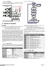
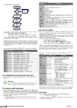
How CMGSM stores a received message:
START
Message received
? D3700
WAIT 1s
WRITE
Phone number
INTO
D3710-D3719
0x0000
ELSE
WRITE
Text of SMS
INTO
D3720-D3799
WRITE
0x0001
INTO D3700
END
Every register of
Phone number
or
Text
contains two characters. String of
characters ends with special character 0x00. Examples:
String with one character – “A”: D3720 = 0x0041
String “TEXT”: D3720 = 0x4554, D3721 = 0x5458, D3722 = 0x0000
String “HELLO”: D3720 = 0x4548, D3721 = 0x4C4C, D3722 = 0x004F
If length of phone number is exactly 20 characters (or 160 characters of text) the
character 0x00 at the end is omitted!
CMGSM contains a queue of up to 100 SMS messages. After the queue is full all
other SMS messages are discarded. If a power failure occurs all received messages
in the queue are lost. Base of
Recv Record
(D3700) may be changed to another D
or R register via configuration key REGRECV. No other registers are changed than
the necessary ones.
Example of receiving of message “TEST MESSAGE.” from phone “+420123456789”:
Register
Value
Description
D3700
0x00
01
RecvFlag: new message
D3710
0x342B
RecvOrigAddress, characters “+” and “4”
D3711
0x3032
RecvOrigAddress, characters “2” and “0”
D3712
0x3231
RecvOrigAddress, characters “1” and “2”
D3713
0x3433
RecvOrigAddress, characters “3” and “4”
D3714
0x3635
RecvOrigAddress, characters “5” and “6”
D3715
0x3837
RecvOrigAddress, characters “7” and “8”
D3716
0x0039
RecvOrigAddress, characters “9” and end of string
D3720
0x4554
RecvUserData, characters “T” and “E”
D3721
0x5453
RecvUserData, characters “S” and “T”
D3722
0x4D20
RecvUserData, characters “ ” (space) and “M”
D3723
0x5345
RecvUserData, characters “E” and “S”
D3724
0x4153
RecvUserData, characters “S” and “A”
D3725
0x4547
RecvUserData, characters “G” and “E”
D3726
0x002E
RecvUserData, characters “.” and end of string
4.2
GSM Data Connection (Data Call, CSD)
Data connection can be established anytime, even if GPRS communication is in
progress.
Warning
There is no security mechanism against unauthorized data connection to
PLC. So it is highly recommended to set security in PLC (password).
4.3
Service SMS Commands
Received SMS message with string ‘#!’ and password at the beginning are
considered to be
service SMS commands
. These messages are not forwarded to PLC,
but they are processed in CMGSM. Device will check for a valid access code (ACODE
parameter in configuration) and if the access code is valid, the message is searched
for keywords. Only one keyword in every SMS is executed.
Example of this SMS:
#!1234 INFO
#!998877 CONFIG
Table of all keywords:
Keyword
Description
INFO
STATE
Device will respond with SMS describing its current status, e.g.
CMGSM: NETWORK=Vodafone CZ 77%
IN1=off
OUT2=off
CSD=no connection
GPRS=no connection
PLC=connected
CMGSM v8.2
RESET
Device will respond with confirmation SMS and restart itself. PLC is
not affected.
This command is used after change of configuration in PLC register
to accept the changes by CMGSM.
CONFIG
Device will respond with current configuration. (Current
configuration is a default configuration with some values changed by
configuration string in PLC, see Chapter 5 – Configuration.)
FACTORY
CMGSM will respond with confirmation SMS. CMGSM will write
default configuration to attached PLC and restart itself.
ON
Activate digital output OUT2
OFF
Deactivate digital output OUT2
4.4
TCP over GPRS
One of the primary functions of this device is to establish and maintain TCP
connection from PLC to a server. In order to achieve this goal FBs-CMGSM has to
make following steps after power up:
Establish connection to PLC via serial port. Parameters of the serial port are: 9600
baud, 7 data bits, EVEN parity, 1 stop bit, no hw handshake (it is default FATEK
settings for all serial ports), address 01h.
After power on the FBs-CMGSM will proceed steps:
Read configuration from PLC register D3900 – D3999.
Login to the GSM network, using
PIN
from configuration.
Attach to GPRS, using
APN
,
USER
and
PASSWD
from configuration.
Establish and maintain TCP connection to
SERVER
on port
PORT
.
CMGSM will try indefinitely to read configuration from PLC at the beginning. If there
is no serial communication between CMGSM and PLC device will not login into the
GSM network! If there is no configuration in PLC or the configuration is damaged or
other problem occurs CMGSM writes default configuration into the PLC.
GPRS can be controlled and monitored via set of registers in PLC and via
configuration:
Registers
Caption
Description
D3510
GprsCommand
0=no connection (written by PLC)
1=open connection (written by PLC)
D3511
GprsState
0x00=no connection, idle
0x01=connecting
0x80=connected
0x81=disconnecting
D3512
GprsCntErr
Error counter for connection
D3516-D3517
GprsCntUp
Data
counter,
direction
UP
(= PLC
TCP), D3516 LSB
D3518-D3519
GprsCntDown
Data
counter,
direction
DOWN
(= TCP
PLC), D3518 LSB
D3520-D3523
GprsLocalIP
Local IP address if connected. “0.0.0.0” if
not connected. (D3520=MSB)
Example:
If local IP address is 147.32.80.1, then
D3520 … 0x0093 (147d)
D3521 … 0x0020 (32d)
D3522 … 0x0050 (80d)
D3523 … 0x0001 (1d)
D3524
GprsLocalPort
Local TCP port if connected, 0 if not
connected
D3525-D3528
GprsRemoteIP
Remote IP address if connected. “0.0.0.0”
if not connected. (D2425=MSB)
D3529
GprsRemotePort
Remote TCP port if connected, 0 if not
connected
This range of registers cannot be used for any other purposes!
GPRS diagnostic is part of Diagnostic (see chapter Diagnostic). Base of
Diag Record
(D3500) may be changed to another D or R register via configuration key REGDIAG.
4.5
Events
Device can detect special events and send a warning about them as a SMS:
Connection to PLC failure/restore
It is needed to set parameter
MASTER
in configuration for both of these events,
see chapter 5.2 Basic Parameters.
PLC1.ir


