background image

Shark     Byte

3

Shark Byte Video Transmitter TX5M.1

The Shark Byte TX5M.1 is a digital HD 720p 60fps medium range video transmitter capable of delivering up to 500mw on 5.8GHz. The TX5M.1 works with the Shark Byte 
RX5.1 goggle module to transmit video, and a remote controller to control the parameters for transmitter and camera wirelessly. 
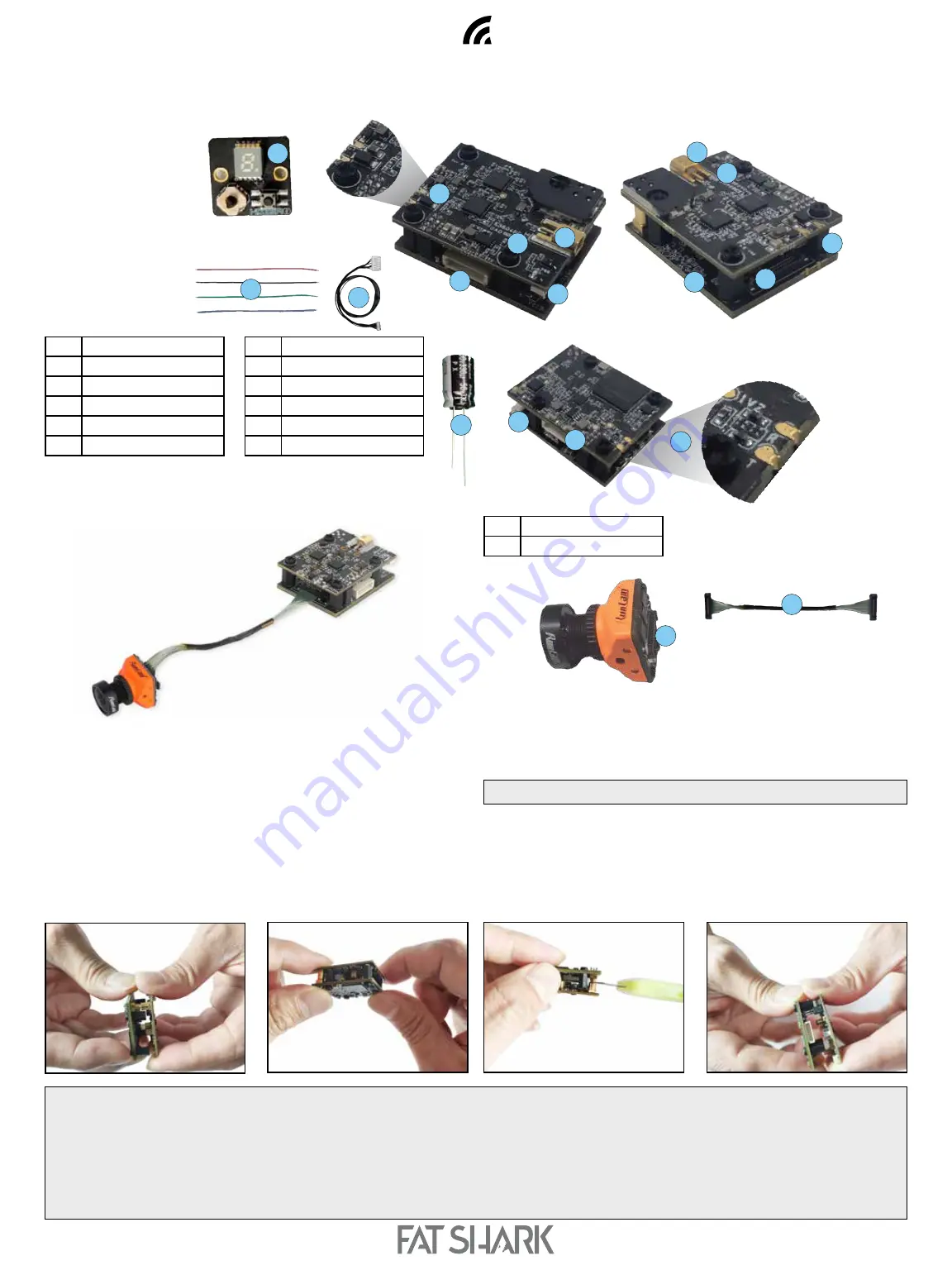
The Shark Byte TX5M.1 consists of a Runcam Nano HD camera and a video transmitter (VTX) made up of two PCBs.

Runcam Nano HD

GND

TX

RX

7–26V

5

5

9

8

8

1

2

2

4

6

6

7

7

3

10

12

11

1

Power/UART cable

2

FW Update Connector

3

UART (3.3V)

4

MIPI Connector

5

Power IN (7-26V)

6

Power LED (red)

1

MIPI Camera

2

MIPI cable

7

MMCX Antenna Connector

8

Key Pad Connector

9

Status LED (blue)

10

Key Pad Cable

11

Key Pad

12

330 µF Capacitor

1

2

WARNING:

 DO NOT 

apply power to the RF board until the boards are fully assembled and ready to operate. If you apply power to the RF board without the BB board 

attached it may result in permanent damage.

DO NOT 

power ON the VTX without an appropriate 5.8GHz antenna connected to the MMCX connector. If you power ON the VTX without an antenna connected, it may result in 

permanent damage.

DO NOT

 touch the video transmitter during or immediately after operation, wait for it to cool down. It is normal for the VTX to become hot during or after operation.

DO NOT

 use the VTX for an extended period when the temperature is high or if there is poor ventilation. If the VTX does not get adequate airflow for cooling during operation,  

it may overheat and enter overheat protection mode, which will reduce range performance. 

WARNING:


Use extreme caution when separating the boards with a knife. 

Power input range is 7V – 26V (2S – 6S). A large capacitor (220+µF) is required to 
be mounted in parallel with the power input connector to avoid voltage spikes (and 
subsequent damage) to the VTX. 

DO NOT

 power the VTX without a capacitor on the power input.

Always press and pull on the actual connectors during assembly or disassembly, never 
pull on the wires to remove a connector.  
Solder all of your connections to the boards before assembly. 

ASSEMBLING THE TWO CIRCUIT BOARDS

1.  Align the 8 pin connector between the two boards and begin to make the 

connection, but only insert the pins far enough to establish alignment, don’t press 
them together yet.

2.  Align the coaxial connector between the two boards, and press the boards together 

with a thumb and fore-finger directly above and below the coaxial connector. The 
coaxial connector will snap together when it connects. At the same time, use your 
other hand to press the 8 pin connector together.

DIS-ASSEMBLING THE TWO CIRCUIT BOARDS

1.  Hold the assembly on it’s side to present the coaxial connector between the two 

boards to the side. Hold the boards from above.

2.  Align a knife blade at the separation between the top and bottom of the connector. 
3.  Press down with the knife, away from your hand holding the boards, and twist the 

knife blade to separate the top of the connector from the bottom. The connector 
will pop apart when it releases. 

4.  Once the connector pops apart, gently separate the 8 pin connector between the boards, 

Summary of Contents for Shark Byte RX5.1

Page 1: ...is not covered under warranty Shark Byte Shark Byte User Manual Rev 121220 DDMMYY For more product information please visit www fatshark com All Rights Reserved THIS MANUAL COVERS NOT INCLUDED REQUIRE...

Page 2: ...Video Transmitter TX5S 1 6 TX5S 1 Connection Diagram 6 TX5S 1 Specifications 7 Adjusting VTX and Camera Parameters with the Keypad 7 VTX PID Configuration by RC controller 8 VTX Parameters 8 Camera P...

Page 3: ...for cooling during operation it may overheat and enter overheat protection mode which will reduce range performance WARNING Use extreme caution when separating the boards with a knife Power input ran...

Page 4: ...ed for use in racing drones and does not use a heat sink in an effort to maintain minimal weight and form factor It is expected proper cooling airflow will be provided to the VTX board during operatio...

Page 5: ...nsions Camera 14 x 14mm with 19 x 19mm adaptor VTX 25 x 32 x 12 mm Coaxial cable 85mm Mounting Pattern VTX 20 x 20mm M2 Operating Frequencies Transmitting Power Power Consumption 25mW 5 7W 200mW 8 2W...

Page 6: ...ontrol the parameters for transmitter and camera wirelessly The Shark Byte TX5S 1 consists of a Runcam Nano HD camera and a video transmitter VTX made up of a single PCBs Power input range is 7V 26V 2...

Page 7: ...ft Press Right Right VTX The select button 2 and 7 segment LED display 3 are used exclusively for setting VTX parameters To change channel Short press the select button 2 the 7 segment LED display 3 w...

Page 8: ...down and together and returns back to idle state if you choose exit from VTX menu PID settings for your flight controller can be managed through the VTX parameters menu as well Camera parameters The V...

Page 9: ...ot access the camera parameters with the RC control if the keypad is attached to the VTX IMPORTAN T If you apply left control on the left stick at any time during camera setup it will exit the camera...

Page 10: ...Shark Byte 10 50FPS 60FPS SWITCHING Note Long UP press the joystick button of the attached keypad will enter the menu directly...

Page 11: ...flight 1 Connect the Flight Controller to Betaflight 4 x MultiWii API version 1 41 or above 2 Select Ports 3 Select UART port that is connected with VTX and set baud rate to 115200 4 Save 5 Select Con...

Page 12: ...ltitude Home Distance Home Direction j Craft Name k Cross hair l Throttle Position m VTX Channel n Post flight statistics Note For RSSI and GPS data to work the following must be true Your RC receiver...

Page 13: ...to right as R key and middle as M key Video mode is defined as HDMI outputting live video and setup mode is defined as HDMI outputting setting screen Long press L key press and hold for 3 seconds the...

Page 14: ...Shark Byte 14 ASPECT RATIO The goggle module always receives 1280x720 HD video from the VTX In 4 3 mode the receiver will output 960x720 video by cropping both sides of received video...

Page 15: ...onto root directory of a SD card insert the SD card into the VRX module 3 Power on the VRX module and wait for Success to be shown on the video display The firmware will be automatically deleted from...

Page 16: ...ts VTX antenna connection loose Ensure the VTX antenna and any adapters in use are secured and solidly connected If the antenna becomes disconnected during operation it will degrade performance and ma...

Reviews: