


9
4. To add a stored preset as a Tour, twist the Zoom handle or press Zoom Key (Programmed preset will scroll). To remove a stored preset from the Tour, press
the Home key, blank position mark (===) will be displayed. You can overwrite the programmed position.
5. To place functions other than preset, press Tour, Ptrn, or Scan for Tour, Pattern or Auto Scan respectively and the use
zoom
handle or key to select No.
6. Repeat Step through 5 for each desired position. Each title will be displayed on top of the line.
7. Up to 36 Presets, Tours, Patterns Scans can be selected for a Tour. You can expand the
Tour
sequence by calling other programmed tours.
Push the
Joystick
handle to right or left while the cursor is on the top of the line (TOUR 0) to select another page of the Tour menu. (TOUR 0)
8. You can enter a title for the selected Tour by twisting the
Joystick
while the cursor is on the top of the line (TOUR 0). Rotate the handle clockwise or
counterclockwise to scroll through the alphanumeric characters. Push the handle to the right or left to select the next or previous digit.
9. Select Save and Exit by pushing the
Joystick
to the right. Press
ESC
to exit the program without saving.
NOTE: Press the Home key at a programmed position to delete programmed function. In the Tour mode, in conjunction with preset and Auto Scan,
you can make the camera travel from a preset position to another preset position at a specific speed.
Example:
Preset 00>00>003>004>005>006, Auto Scan 0 starts at preset 00, ends at preset 003, Auto Scan 0 starts at preset 005, ends at preset
006; Tour 00, 00, A0, 004, A0.
~3 4 5~6, repeat
where : Quick move, ~ : Programmed speed
3.8 Pattern
(Fourth 4 Item of the Main menu / Shortcut:
Ptrn
)
The Pattern feature records user control of the selected dome camera for up to 40 seconds. Up to four 4 patterns can be stored and played back by pressing
No.+
Ptrn
keys subsequently.
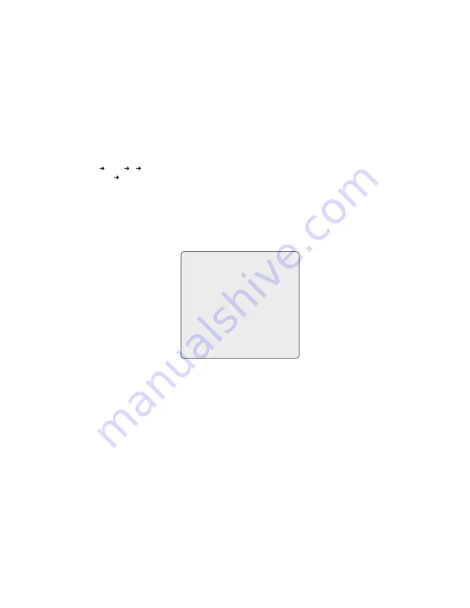
PATTERN SETUP
NO. TITLE SEC
0: xxxxxxxxxxxxxxxx 000
0: xxxxxxxxxxxxxxxx 04
03: xxxxxxxxxxxxxxxx 00
04: xxxxxxxxxxxxxxxx 00
TOTAL: 07
SAVE AND EXIT (ESC TO CANCEL)
HOLD DOWN CTRL KEY
WHILE RECORDING.
Follow steps below to program the Pattern:
. Press
Menu
key to display the main menu on the monitor.
. Scroll down to PATTERN and push the
Joystick
to the right. Or simply press the
Ptrn
key rather than use the Main Menu.
3. Select the empty Pattern number to be programmed by pushing the
Joystick
up or down. If last column is not 000, a pattern has already been recorded.
Patterns can be over written.
4. Press and hold down the
Ctrl/PGM
key while controlling the camera direction and zoom with the
Joystick
. Your controls will be automatically recorded
until you release the
Ctrl/PGM
key. You can repeat this procedure until you have the pattern you want. Previously recorded patterns will be overwritten
each time you do this.
5. Scroll down to the Save and Exit option and push the
Joystick
to the right to save and exit.
6. You can title the selected Pattern by twisting the
Joystick
. Rotate the handle clockwise or counterclockwise to scroll through the alphanumeric characters,
push the handle to right or left to select next or previous space.
7. Pressing
ESC
will not save your information and exits to the previous mode.
7.
Press the
Home
key at any programmed position to delete the programmed pattern.
NOTE: If total recording time reaches 240 seconds, it will automatically stop for a moment and restart recording. Previous data will be overwritten.


