Fastrax EDC-141E Installation And Operating Manual Download Page 18

8

3.6  Shortcut of Preset Program

Select a view to be stored (direction of the camera, zoom and focus), then press No. (

to 

240

), and then press 

Pgm

Prst 

subsequently. The current view will 

be stored to the selected preset number if position is empty. If selected preset number is not empty, „PRESET EXISTING” message will be displayed on the 
monitor and ask to overwrite. 

Example:


1

0

Pgm 

Prst 

will store current view as preset No. 0. In this case, focus and Iris mode will be programmed as Auto, dwell time will be set 

to 3 sec. 

3.7  Tour  

(THIRD ITEM OF THE MAIN MENU / SHORTCUT: 

Tour

)

There are 8 programmable Tours. Each Tour consists of up to 4 Preset positions, Patterns, Scans or other Tours (second-level). Using second-level Tours, it 
can be expanded to over 300 functions in a single Tour. However Tours in second level Tour will be ignored when called by a Tours. The following example 
illustrates this concept:

If 

 Tour has Preset   Preset   Tour   Tour3 and


 Tour has Preset3   Preset4   Preset5   Tour4 and


 Tour3 has Preset6   Pattern and


 Tour4 has Preset7.


 Tour executes as follows:


 Preset   Preset   Preset3   Preset4   Preset5   Preset6   Pattern   


 Preset   ... (Repeat)


 Tour executes as follows:


 Preset3   Preset4   Preset5   Preset7   Preset3 ... Repeat


 (Tour4 is still valid if called directly from Tour.)

xxxxx :  

6 digits of title for tour label

=== :  

blank preset position

SCAN TYPE :   Max (Normal)/ Slow V. Scan/ Fast V. Scan
DWELL :  

03-99 Sec

003 :  

Preset 003 (~40)

A08 :  

Auto Scan 08 (~8)

P0 :  

Pattern 0 (~4)

T0 :  

Tour 0      (~8)

Follow the steps below to program the Tours:

.  Press 

Menu 

to display the main menu on the monitor. Scroll to Tour and push the 

Joystick 

to the right to enter the Tour menu. Or just press the Tour key  

  on the keyboard.
.  Choose an empty location to be programmed by pushing the 

Joystick 

up, down, right, or left. 

3.  To see a stored preset view, use the 

Joystick 

to move the cursor to a stored position. By pressing 

Prst 

key, the camera will move to the stored Preset view.
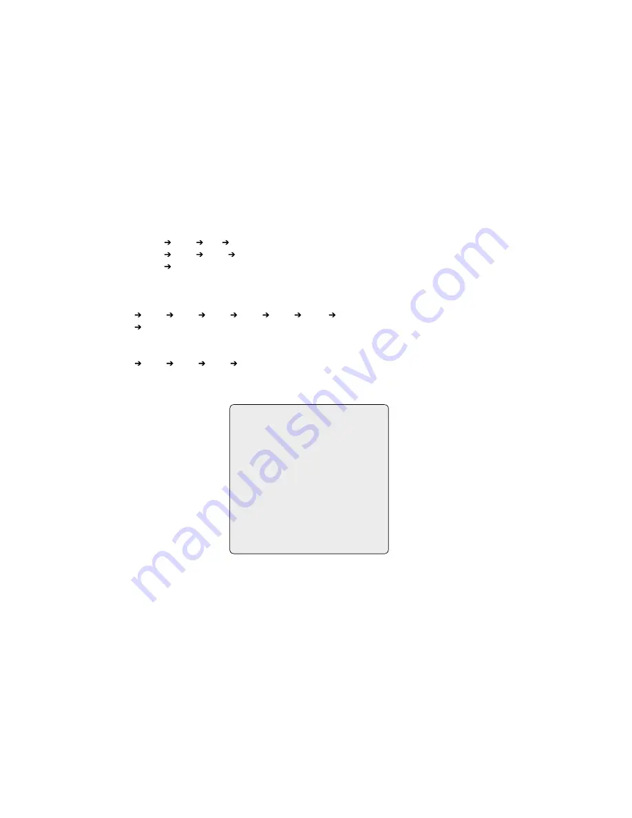
GUARD TOUR SETUP

TOUR 0       : xxxxxxxxxxxxxxxx
SCAN TYPE  : NORMAL
DWELL          : 03

=== === 003 === === === ===
A08 === === === === === ===
=== T0 === 00 === === ===
=== === === T08 === === ===
=== === === === === === ===
=== === === === === === ===
SAVE AND EXIT (ESC TO CANCEL)
PRESS FUNCTION KEY AND ROTATE 
JOYSTICK TO SELECT NUMBER.

Summary of Contents for EDC-141E

Page 1: ...Installation and Operating Manual Fastrax Dome Video Camera for Ceiling and Wall Mounting EDC 141E EDC 143E EDC 144E EDC 142E2...

Page 2: ...15 3 1 Selecting Dome Camera 15 3 2 Accessing On Screen Menu Utility 15 3 3 How To Control On Screen Menu Utility 15 3 4 Auto Scan 16 3 5 Preset 17 3 6 Shortcut of Preset Program 18 3 7 Tour 18 3 8 P...

Page 3: ...and wipe gently NOTE This is a class A digital device This digital device can cause harmful interference in a residential area in this case the user may be required to take appropriate corrective acti...

Page 4: ...improving picture quality when you assemble bubble ring ass y up to 255 multiplexer Alarm Input up to 8 Sensor Siren Flashing light Alarm Output up to 4 J box Master keyboard up to 3 Slave keyboards...

Page 5: ...h body and base of the camera Different version will not support alarm input and output The dome camera is for use in surface mounting applications and the mounting surface should be capable of suppor...

Page 6: ...24VAC STP AWG 24 Sensor Alarm input up to 8 Siren Light Alarm output up to 4 BNC Alarm output 1 2 Alarm input 1 4 Power 24VAC Dome1 Dome1 Alarm output 3 4 Alarm input 5 8 Monitor BNC RS 485 Half Dupl...

Page 7: ...Multiplexer Figure 5 Single Multiplexer Rear Keyboard controller Power 24VAC BNC Main Monitor BNC BNC RS 485 Pin No 4 RS 485 Pin No 6 J Box Back J Box Front AWG 24 Power 24VAC Power 24VAC Spot Monito...

Page 8: ...ox Front AWG 24 Power 24VAC Power 24VAC Spot Monitor 1st Multiplexer BNC 2nd Multiplexer 2nd Main Monitor Spot output of the first multiplexer to be connected to 16th input of the second multiplexer A...

Page 9: ...K B 1st Multiplexer BNC 2nd Multiplexer 2nd Main Monitor Spot Monitor for Slave K B Keyboard controller Slave Rear Spot output 1 of the first multiplexer to be connected to 16th input of the second mu...

Page 10: ...iplexer nth spot out of the 2nd multiplexer to be connected to the nth spot monitor Each user will see the picture of the selected camera 1 31 n on nth spot monitor of the Mux 2 by selecting camera No...

Page 11: ...the cable for communication terminated by setting the appropriate DIP switch Without proper termination there is potential for control signal errors Total length of the cable for communication should...

Page 12: ...he service provider Example Port 1 Dome 1 Port 2 Dome 2 Port 16 Dome 16 If more than 16 dome cameras are installed using two or more multiplexers ID of the dome camera should be ID of MUX x No of came...

Page 13: ...d On On Reserved S W On Off Function D1 S4 1 Enable Disable Alarm D2 S4 2 PAL NTSC NTSC PAL D3 S4 3 Endless D4 S4 4 RS 422 RS 485 RS 422 RS 485 D5 D6 D7 Protocol S5 1 S5 2 S5 3 Off Off Off Fastrax Pel...

Page 14: ...m input GND Ground NOTE All the connectors marked GND are common Connect the ground side of the Alarm input and or alarm output to the GND connector NC NO 1 TO 4 Normal Close or Normal Open Alarm Out...

Page 15: ...Accessing On Screen Menu Utility You can call up the On screen menu utility on your monitor by pressing MENU key on the keyboard controller the following On screen menu utility will appear 3 3 How to...

Page 16: ...the Joystick downward to select END ANGLE Hold down the Ctrl PGM key while moving the Joystick to select the end position and zoom The end position angles should be larger than start position Release...

Page 17: ...After selecting a blank position press and hold Ctrl PGM use the Joystick to control the direction of the camera and lens Ctrl Joystick 5 After aiming the camera view direction and lens control relea...

Page 18: ...r2 has Preset3 Preset4 Preset5 Tour4 and Tour3 has Preset6 Pattern1 and Tour4 has Preset7 Tour1 executes as follows Preset1 Preset2 Preset3 Preset4 Preset5 Preset6 Pattern1 Preset1 Repeat Tour2 execut...

Page 19: ...e Quick move Programmed speed 3 8 Pattern Fourth 4 Item of the Main menu Shortcut Ptrn The Pattern feature records user control of the selected dome camera for up to 240 seconds Up to four 4 patterns...

Page 20: ...the Joystick up or down and push to right to enter the detail menu 2 Select the alarm input number by pushing the Joystick up or down and select the column you wish to setup Selected position will be...

Page 21: ...o the right Press ESC to exit the program without saving 6 Pressing the Home key will delete programmed data Angles will be turned immediately 3 11 Privacy Zone Seventh Item of Main menu Hide up to 8...

Page 22: ...tendable up to 2x of digital range 4x Zoom is extendable up to 4x of digital range MAX Zoom is extendable Max digital Zoom range EDC 142E2 OFF MAX NIGHT SHOT CONTROL FOCUS CONTROL FOCUS SETUP MODE AUT...

Page 23: ...andle WB SETUP MODE AUTO R GAIN 210 B GAIN 155 EXIT ESC TO EXIT EDC 141E EDC 144E MODE MANUAL AUTO RGAIN 0 255 BGAIN 0 255 Use the AUTO mode for normal use RGAIN BGAIN modes are controllable only in M...

Page 24: ...t filter is automatically turned on and off more dark condition than AE DARK AE DSS automatic exposure without switching IR Cut filter SLOW SHUTTER 1 60 1 30 1 15 1 8 1 4 1 2 1 50 1 25 1 12 1 6 1 3 1...

Page 25: ...2 000 1 5 000 1 10 000 1 1 1 2 1 3 1 6 1 12 1 25 1 50 1 100 1 120 1 250 1 500 1 1 000 1 2 000 1 4 000 1 10 000 WDR MODE Wide Dynamic Range Technology uses two shutter speeds in alternative video fiel...

Page 26: ...matically goes to Preset Tour Pattern Auto Scan after the keyboard controller has been idle for a amount of time For example if the Joystick controller is idle for 10 seconds the camera goes to preset...

Page 27: ...y it is recommended that you set North as a Preset Recall the North Preset before enabling the directional title DOME OSD DISPLAY All display or title will disappear when DOME OSD DISPLAY sets OFF ARE...

Page 28: ...r Angle is not sufficient enough to avoid ceiling obstructions please adjust Origin Offset of tilt angle as described below INITIALIZE DATA INITIALIZE DATA FACTORY DEFAULT ERASE PROGRAMMED DATA EXIT E...

Page 29: ...ble for Keyboard is proprietary Cable for video is shielded Check termination of Video Dome cameras lose their positions Reset the cameras using the Dome configuration menus Check that the dome camera...

Page 30: ...reset or pattern that is running and alarm names The display of each type of name setting can be enabled or disabled When the display of camera or area title name is enabled the information appears on...

Page 31: ...4 ON Turn On Relay 1 4 OFF Turn Off Relay 10 ON Night Shot on 10 OFF Night Shot off 11 ON BLC on 11 OFF BLC off 12 ON Digital Zoom on According to digital zoom setting 12 OFF Digital Zoom off 13 ON D...

Page 32: ...c or 3x up to 240sec in total Tours Up to 8 User programmable guard tours with vector scan Consisting of 42 presets and other functions with individual dwell time 3 to 99sec Selectable fast or slow ve...

Page 33: ...e specific dome settings Adresses Up to 999 Dome ID s 3999 by software setting Up to 999 Dome ID s Up to 999 Dome ID s 3999 by software setting Keyboard control Direct mode control with Eneo EDC KBD M...

Page 34: ...t Indoor Dome Housing with Clear Bubble 6 5 24VAC 74136 EDC OPS 2 24V Pendant Mount Outdoor Dome Housing with Sunshield Tinted Bubble 6 5 24VAC 74089 EDC CR1 Converter RS 232 RS 485 Repeater RS 485 74...

Page 35: ...35 8 Dimensional Drawings Dimensions mm 99 0 45 R 3 R5...

Page 36: ...Exclusive distribution through specialised trade channels only VIDEOR TECHNICAL E Hartig GmbH Carl Zeiss Stra e 8 63322 R dermark Germany Tel 49 0 6074 888 0 Fax 49 0 6074 888 100 www videortechnical...

Reviews: