-17-
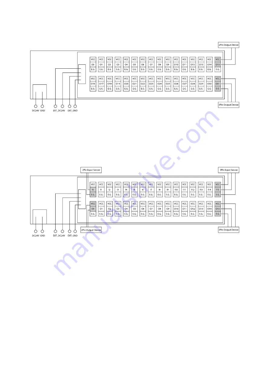
5.2 External Wiring Diagram (Ezi-IO-CT-O32N-E)
All e-CON connector signals consist of inputs. It can receive up to 32 digital data from peripheral devices.
Figure 5-3. Ezi-IO-CT-O32N-E
5.3 External Wiring Diagram (Ezi-IO-CT-I16O16N-E)
The e-CON connector signals are a combination of inputs and outputs. It can receive up to 16 digital data from
peripheral devices and can output up to 16 digital data from peripheral devices.
Figure 5-4. Ezi-IO-CT-I16O16N-E
* The VCC and E.G. are supplied by the Input/Output power connection connector(CN5).
* Example) 2Pin Input Sensor: Limit switch, etc.
3Pin Input Sensor: Location sensor, photo sensor, proximity sensor, etc.
2Pin Output Device: Brake, Solenoid, Photocoupler, etc.


