- 4 -
8
) starts flashing. Both LEDs, however, indicate only the voltage status of the correlator box
accummulators. The charging status of the laptop accummulator is indicated in the task bar on the display of
the laptop.
If wireless communication between the laptop and the correlator box is desired, you can establish such
wireless communication by means of the optional Bluetooth dongle (see Chapter 1.3.4). In order to establish
wireless communication, detach the USB connection cable (Illustration 1-3,
point 2
) from the laptop.
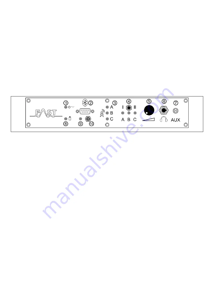
Then connect the Bluetooth dongle to the interface as shown in Illustration 1-4,
point 2
. As soon as the
Bluetooth mode has been activated on the laptop, the correlator box can be switched on through the key
point 10
). Now the red LED as shown under
point 9
is lit, and the correlator box is
ready for communication via the Bluetooth interface.
Illustration 1-4: Control panel
Point 3
in Illustration 1-4 shows the so-called Squelch indicator. This indicator visualises the availability
of radio signals transmitted by the measurement boxes as soon as the correlator programme has been started
on the laptop. When the red measurement box for channel A has been switched on, the first LED is lit red.
As soon as the blue measurement box with the sensor for channel B has been switched on, the second LED
is lit blue, and the third LED is lit yellow when a measurement box with channel C has been activated.
According to the selection of the channels in the correlator programme, only two LEDs are lit at the same
time. If a measurement box is activated and the corresponding LED is not lit, please check the aerials of the
measurement boxes and the aerial of the correlator (see Illustration 1-5,
point 1
), as well as the selected
channel(s) in the correlator programme,
The radio signals can be received and listened to through headphones to be connected to the jack as shown
under
point 6
(Illustration 1-4). In order to listen to the signals with the headphones, just select the
corresponding channel with the channel selection knob as shown under
point 4
. If the knob is in the
central position, no channel has been selected and neither the internal loudspeakers nor the headphones issue
a tone. If the channel selection knob is turned left to position 1, either signals of channel A or signals of
channel B can be listened to. The settings in the correlator programme determine which channel can be
heard. Position 2 (right) lets you select channel B or channel C for rendering purposes. The signals are
normally rendered through the internal loudpseaker which is installed under the laptop. As soon as the
headphones have been plugged into the jack as shown under
point 6,
the correlator box automatically


