Fast DP9D Owner'S Manual Download Page 74


TIGHTENING HARDWARE


TIGHTENING HARDWARE  Dry DuraPlacer 9 / 13 / 14 Ton - 40' / 60'  


Page 58


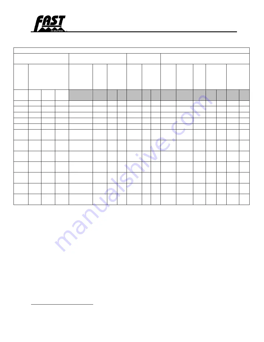
SAE Face Seal and O-Ring Stud End Fitting Torque Chart


SAE Face Seal and O-Ring Stud End Fitting Torque Chart - Standard Pressure-Below 27.6 MPA (4,000 PSI)


Nominal Tube OD


Hose ID


O-Ring Face Seal/


Tube Swivel Nut


Bulkhead Jam 

Nut Torque


O-Ring Straight, Adjustable, and External 

Port Plug Stud Ends

6


Metric


Tube 

OD


Inch Tube OD


Thread 

Size


Swivel


Nut 

Hex 

Size


Tube Nut 

Swivel 

Nut 

Torque


Jam 

Nut 

Hex 

Size


Jam Nut 

Torque


Thread


Size


Straight


Hex 

Size

7


Adj 

Lock 

Nut 

Hex 

Size


Steel or 

Gray Iron 

Torque


Aluminum 

or Brass 

Torque

8


mm


Dash


Size


in.


mm


in.


in.


N-m


lb.-

ft


N-

m


lb.-

ft


in.


in.


in.


N-m


lb.-

ft


N-m


lb.-ft


5


-3


0.188


4.78


3/8-24


5/8


9/16


12


9


8


6


6


-4


0.250


6.35


9/16-18


11/16


16


12


13/16


32


24


7/16-20


5/8


5/8


16


12


11


8


8


-5


0.312


7.92


1/2-20


3/4


11/16


24


18


16


12


10


-6


0.375


9.53


11/16-16


13/16


24


18


1


42


31


9/16-18


3/4


3/4


37


27


25


18


12


-8


0.500


12.70


13/16-16


15/16


50


37


1-1/8


93


69


3/4-16


7/8


15/16


50


37


33


25


16


-10


0.625


15.88


1-14


1-1/8


69


51


1-5/16


118


87


7/8-14


1-1/16


1-

1/16


69


51


46


34


20


-12


0.750


19.05


13/16-12


1-3/8


102


75


1-1/2


175


129


11/16-

12


1-1/4


1-3/8


102


75


68


50


22


-14


0.875


22.23


13/16-12


102


75


175


129


13/16-

12


1-3/8


1-1/2


122


90


81


60


25


-16


1.000


25.40


17/16-12


1-5/8


142


105


1-3/4


247


182


15/16-

12


1-1/2


1-5/8


142


105


95


70


32


-20


1.25


31.75


1-11/16-12


1-7/8


190


140


2


328


242


1-5/8-

12


1-3/4


1-7/8


190


140


127


93


38


-24


1.50


38.10


2-12


2-1/4


217


160


2-3/8


374


276


1-7/8-

12


2-1/8


2-1/8


217


160


145


107


50.8


-32


2.000


50.80


2-1/2-

12


2-3/4


2-3/4


311


229


207


153


6

 Tolerance is +15%/-20% of mean tightening torque unless otherwise specified.


7

  The  straight  hex  wrench  sizes  listed  apply  to  connectors  only  and  may  not  be  the  same  as  the 

corresponding plug of the same thread size.


8

 These torques were established using steel plated connectors in aluminum and brass.


Summary of Contents for DP9D

Page 1: ...DP9D DP13D DP14D 40 60 OWNERS MANUAL DRY DURAPLACER OWNERS MANUAL 2023...

Page 2: ...820070 Dry DuraPlacer 9 13 14 Ton 40 60 2023 09 27...

Page 3: ...otect Against Noise 3 Prac ce Safe Maintenance 3 Support Raised Equipment 4 Avoid Hea ng Near Pressurized Fluid Lines 4 Avoid High Pressure Fluids 4 Inspect Li Circuit Hoses 5 Store A achments Safely...

Page 4: ...Operator s Manual 19 Pre Opera on Checklist 19 AXLES TIRES and TRACKS 20 Se ng Axle Width 20 Axle Width Chart Singles 21 Axle Width Chart Tracks 22 Checking Tire Pressure 23 Checking Wheel Nuts 23 Tr...

Page 5: ...ders O the Machine 36 Cau on for All Machines 37 Unfolding Extending the Toolbar 37 HYDRAULIC FLOW 39 Regula ng Hydraulic Flow to the Pump 39 Load Sensing Closed Center System LS Closed 39 Pressure Co...

Page 6: ...51 Support the Machine Properly 52 Avoid High Pressure Fluids 52 Preven ng Hydraulic System Contamina on 52 Replace Hydraulic Hoses 53 Tightening Hardware 53 PREPARING FOR STORAGE 54 Removing from Sto...

Page 7: ...Dry DuraPlacer DP9D DP13D DP14D Page v...

Page 8: ...ressed as follows Fast Ag Solutions 4130 Commerce Boulevard Windom MN 56101 This warranty shall expire one 1 year after the date of delivery of the new machinery If these conditions are fulfilled Fast...

Page 9: ...ts Clean ____Wheel Drive Turns Freely ____ Review Operating and ____Lubricate Machine ____ Safety Instructions ____Check Tire Pressure ____Frame and Wings Level ____Monitors and Controllers Function _...

Page 10: ...DuraPlacer DURAPLACER SERIAL NUMBER _______________________________ DATE PURCHASED ______________ _____ __________ BIN MANUFACTURER CIRCLE ONE MONTAG LYNX NUMBER OF ROW UNITS _________________________...

Page 11: ...fittings are lubricated see LUBRICATION and MAINTENANCE section in this Manual o Inspect to be sure all nuts are tightened to proper torque and all cotter pins are spread o The tires are properly infl...

Page 12: ...customer aware of all safety precautions that must be followed while using this machine o When the machine is transported on a road or highway at night or during the day accessory lights and devices s...

Page 13: ...possible operate the machine to see that it is functioning properly o Acquaint the customer with any special attachment which will help do a better job o Go over the entire machine for loose or missin...

Page 14: ...3D DP14D Page xii Owner Register Model Number P I N Number Name Address County State Date Purchased Name Address County State Date Purchased Name Address County State Date Purchased Name Address Count...

Page 15: ...vel when going forward WRITE PRODUCT IDENTIFICATION NUMBERS P I N in the Specification section and in the Owner Register Accurately record all numbers to help in tracing your machine should it be stol...

Page 16: ...d WARRANTY is provided as part of Fast Ag Solutions support program for customers who operate and maintain their equipment as described in this Manual The warranty is explained on the warranty certifi...

Page 17: ...ts for service or repairs Substitute parts will void the warranty and may not meet standards for safe and satisfactory operation Warranty is provided as part of Fast Ag Solutions support program for c...

Page 18: ...s Manual the terms CAUTION WARNING and DANGER are used along with the Safety Alert Symbol to indicate the degree of personal safety hazard The term IMPORTANT is used to indicate that failure to observ...

Page 19: ...ear radio or music headphones while operating the machine Protect Against Noise Prolonged exposure to loud noise can cause impairment or loss of hearing Wear a suitable hearing protective device such...

Page 20: ...system unsupported or raised equipment could suddenly lower causing serious personal injury or death If support is not available completely lower wings and frame relieve hydraulic pressure and discon...

Page 21: ...ement hoses Store Attachments Safely Stored attachments such as dual wheels can fall and cause serious injury or death Securely store attachments and implements to prevent falling Keep playing childre...

Page 22: ...ycle used air conditioning refrigerants Handle Agricultural Chemicals Safely Chemicals used in agricultural applications such as fungicides herbicides insecticides pesticides rodenticides and fertiliz...

Page 23: ...S provides specific details on chemical products physical and health hazards safety procedures and emergency response techniques Check the M SDS before you start any job using a hazardous chemical Tha...

Page 24: ...the Operator s view resulting in the machine being operated in an unsafe manner Observe Maximum Transport Speed CAUTION Be sure all bystanders are clear of DuraPlacer IMPORTANT Transport DuraPlacer o...

Page 25: ...rson stays a safe distance away from the machine when it is moving Prior to starting the tractor discuss hand signals and what each signal means to avoid misunderstandings and confusion which could re...

Page 26: ...h to maintain control Properly ballast tractor for towing your machine Refer to tractor Operator s Manual and this Manual to ensure that machine can be safely transported with your tractor Be aware of...

Page 27: ...Shift tractor into a lower gear when transporting down steep slopes or hills never coast Stop slowly Wide turns may be required with the machine in tow Use caution in traffic and in congested areas To...

Page 28: ...eplace missing or damaged safety signs Use this Operator s Manual for correct safety sign placement There can be additional safety information contained on parts and components sourced from suppliers...

Page 29: ...SAFETY SAFETY Dry DuraPlacer 9 13 14 Ton 40 60 Page 13 Wing C B A A C B A B A B...

Page 30: ...SAFETY SAFETY Dry DuraPlacer 9 13 14 Ton 40 60 Page 14 Main Frame Wheel and Tracks...

Page 31: ...y separate from tractor drawbar In addition to the safety features shown here other components systems safety signs on the machine safety messages and instructions in the Operator s Manual contribute...

Page 32: ...Safety Operating and Maintenance information presented in this Manual Do not operate or allow anyone else to operate this equipment until such information has been reviewed Annually review this infor...

Page 33: ...lic System Requirements A tractor hydraulic system with ISO hydraulic couplers is required Five tractor Selective Control Valves SCV at the listed flowrates and pressure are required for following Cir...

Page 34: ...xle Length 11 7m 38ft 6in 11 8m 38ft 8in 11 6m 37ft 11in Toolbar Size s 13 7m 18 3m 40ft 60ft Toolbar Tube Size 18cm x 23cm 7in x 9in rectangular Weight empty 13 108 kg 28 899 lbs 15 512 kg 34 199 lbs...

Page 35: ...nstalled through the drawbar and that a pin and safety chain are installed 4 Inspect all hydraulic lines hoses fittings and couplers for tightness See Tightening Hardware for break in period recommend...

Page 36: ...ort the frame on the rear of the axle with jack stands A 10 ton jack stand shown 2 Remove the axle bolts F and slide the axles B out of shipping holes C 3 Using a forklift D or pallet jack E slide the...

Page 37: ...AXLES TIRES and TRACKS AXLES TIRES and TRACKS Dry DuraPlacer 9 13 14 Ton 40 60 Page 21 Axle Width Chart Singles Figure 2 20k for 1800 Gal 72 144 axle Figure 3 25k for 2400 Gal 80 120 axle...

Page 38: ...AXLES TIRES and TRACKS AXLES TIRES and TRACKS Dry DuraPlacer 9 13 14 Ton 40 60 Page 22 Axle Width Chart Tracks...

Page 39: ...specification Tire Size Pressure 480 80R50 LR176 Singles 359 kPa 3 59 bar 52 psi 580 85R42 LR183 Singles 280 kPa 2 80 bar 41 psi 380 90R46 LR149 Duals 255 kPa 2 55 bar 37 psi Inner 227 kPa 2 28 bar 33...

Page 40: ...e maximum travel speed especially during high ambient conditions Use correct operational techniques o Avoid skidding and tread bar scrubbing on hard surfaces to reduce track wear o Use care when cross...

Page 41: ...vely clean frictional track components belts drive wheels front idlers and mid rollers can generate significant heat if run unlubricated This heat is capable of damaging components Break in and align...

Page 42: ...ck and applicator frame Inspect for cracking A uneven wear B and or chipping or chunking C on rubber surfaces of drive wheels D mid rollers E and idler wheels F Remove any embedded rocks nails or othe...

Page 43: ...of repair or replacement Track Service Service Task Service Action Track Wear Check Track Alignment Track Tension Idler Wheels and Mid Rollers Track Trash Buildup Mid Rollers Oil Level Idler Wheel Hu...

Page 44: ...ne for roughly 200 ft and coast the tractor to a stop Place the tractor in PARK and apply the emergency brake Do not apply braking action during this process as sudden stops can affect track position...

Page 45: ...p screw on the opposite side of the same undercarriage to 300 N m 221 ft lbs Tighten cap screw loosened in Step 2 to the same specification a A single full turn is the standard increment during adjust...

Page 46: ...tor securely around tractor drawbar cage to prevent unexpected separation 5 Check that DuraPlacer hydraulic system is compatible with the tractor s hydraulics Hydraulic System Requirements Change the...

Page 47: ...chain are routed properly to avoid damage When storing the machine keep the safety chain up off the ground and hook it to the machine support assembly on the hitch Always replace a safety chain if one...

Page 48: ...unfamiliar with this type of injury should reference a knowledgeable medical source Such information is available from Deere Company Medical Department in Moline Illinois U S A IMPORTANT Hydraulic ho...

Page 49: ...ase End C II Return Brown Hydraulic Manifold Return D II Pressure Purple Hydraulic Manifold Pressure E III Return Yellow Hopper System Return F III Pressure Red Hopper System Pressure G IV Return Blac...

Page 50: ...essure before disconnecting hydraulic hoses 3 Disconnect hydraulic hoses and place them in their storage position 4 Disconnect safety chain A Adjust Hitch Height Verify machine is parked safely before...

Page 51: ...le and safe speed REDUCE speed over rough or uneven terrain slopes and when turning See Observe Maximum Transport Speed BE SURE SMV emblem reflectors and warning lights are clean visible and in good c...

Page 52: ...ine on a road or highway at night or during the day use accessory lights and devices for adequate warning to operators of other vehicles Check local governmental regulations Various safety lights and...

Page 53: ...ve SCV II in the neutral position for transport If wing fold cylinders are removed or damaged chain wings together to prevent injury or death caused by accidental falling of wings on you or others Unf...

Page 54: ...e sitting still and setting SCV I to continuous down a Hydraulic down pressure gauge E should read between 700 and 1000 psi but see Step 11 below b Down pressure may be adjusted by turning knob F on d...

Page 55: ...5 Move hydraulic lever to Lower Retract position to start pump 6 Adjust tractor flow control until the toolbar shut off deadhead pressure is within the pump s operating parameters Note If the flow lim...

Page 56: ...d pressure is within the pump s operating parameters and lock the jam nut 6 Open the sprayer agitation valve to get desired injection pressure Tractor SCV Functions See SCV Identification Chart for co...

Page 57: ...enabled 1 Turns off hydraulic block pressure Figure 13 SCV III Pushed Forward When the tractor s SCV III is pushed forward the following functions are enabled 1 Engages hopper system for applying Figu...

Page 58: ...toolbar s center section does adjustment should be made on these valves 1 Verify that the main lift hydraulic flow setting in the tractor is set to 9 or 90 If set correctly and problem persists proce...

Page 59: ...stant supply of oil flow to the down pressure system may result in coulters riding out of the ground and could result in structural failure of the toolbar and or hydraulic cylinder components IMPORTAN...

Page 60: ...l speed However the best results are obtained when the ground speed is 8 13 kph 5 8 mph Ground speed variations in the field will automatically be compensated Always operate at a comfortable speed Do...

Page 61: ...n be provided by your Fast Ag Solutions dealer Montag Gen II 2224 Customer Care Kit Montag Gen II Operations Manual The Operator must be familiar with all the instructions and information contained in...

Page 62: ...ic hitch option to raise or lower the front end of the trailer or refer to Adjust Hitch Height for further adjustment CAUTION Add only the amount of product to the tank that is required for the job 1...

Page 63: ...the variables that affect the air pressure are flat rate versus prescription range of rates ground speed number of row units toolbar width if splitters are used density of the product and hose routin...

Page 64: ...e all lubricants Whenever possible store lubricants and containers in an area protected from dust moisture and other contamination Store containers on their side to avoid water and dirt accumulation M...

Page 65: ...rmance requirements Lubrication and Maintenance Intervals Perform each lubrication and service illustrated in this section Each 10 hours or Daily Grease the Toolbar Parallel Linkages both sides Grease...

Page 66: ...that will not accumulate any dirt or debris Before and After Each Season Grease the Wheel Bearings Remove the Tongue Jack remove the Top Cover A from the Jack check the grease level and reinstall the...

Page 67: ...of grease oil or debris On self propelled equipment disconnect the battery ground cable before making adjustments on any electrical systems or welding on the machine On towed implements disconnect its...

Page 68: ...iately with Fast Ag Solutions approved replacement parts Escaping fluid under pressure can penetrate the skin causing serious injury Avoid the hazard by relieving pressure before disconnecting hydraul...

Page 69: ...corrosion exposed wire braids or any other signs of wear or damage Worn or damaged hose assemblies can fail during use and should be replaced immediately See your Fast Ag Solutions dealer for replace...

Page 70: ...ic hoses couplers and fittings Tighten any loose fittings Replace any hose that is damaged or is separating from the crimped end of a fitting 6 Inspect all chemical lines and connections Tighten any l...

Page 71: ...0 885 1350 1000 1700 1250 1580 1160 2000 147 5 M30 660 490 850 625 1290 950 1630 1200 1850 1350 2300 1700 2140 1580 2700 200 0 M33 900 665 1150 850 1750 1300 2200 1625 2500 1850 3150 2325 2900 2150 37...

Page 72: ...0 950 700 1700 1250 2140 1580 2700 2000 3400 2500 1 1 2 990 730 1250 930 990 730 1250 930 2250 1650 2850 2100 3600 2650 4550 3350 Torque values listed are for general use only based on the strength of...

Page 73: ...ed down section of the fitting 2 Install a thimble over the fitting threads to protect the O ring from nicks 3 Slide the O ring over the thimble into the turned down section of the fitting 4 Remove th...

Page 74: ...8 16 12 10 6 0 375 9 53 11 16 16 13 16 24 18 1 42 31 9 16 18 3 4 3 4 37 27 25 18 12 8 0 500 12 70 13 16 16 15 16 50 37 1 1 8 93 69 3 4 16 7 8 15 16 50 37 33 25 16 10 0 625 15 88 1 14 1 1 8 69 51 1 5 1...

Page 75: ...820070 Dry DuraPlacer DP9D DP13D DP14D Page 59 Fast Ag Solutions 4130 Commerce Boulevard Windom MN 56101 1 800 772 9279 Toll Free 1 507 427 3861 Voice 1 507 427 3030 Fax https fastagsolutions com...

Reviews: