


2. Disassembly
When a valve is first received in the shop, it should
be given a visual inspection to note its condition
when removed from service. The valve should
then be carefully dismantled. Proper facilities and
tools should be available. At each stage in the dis-
mantling process, visually inspect all parts of the
valve for evidence of wear and corrosion. If parts
are worn, replace them.
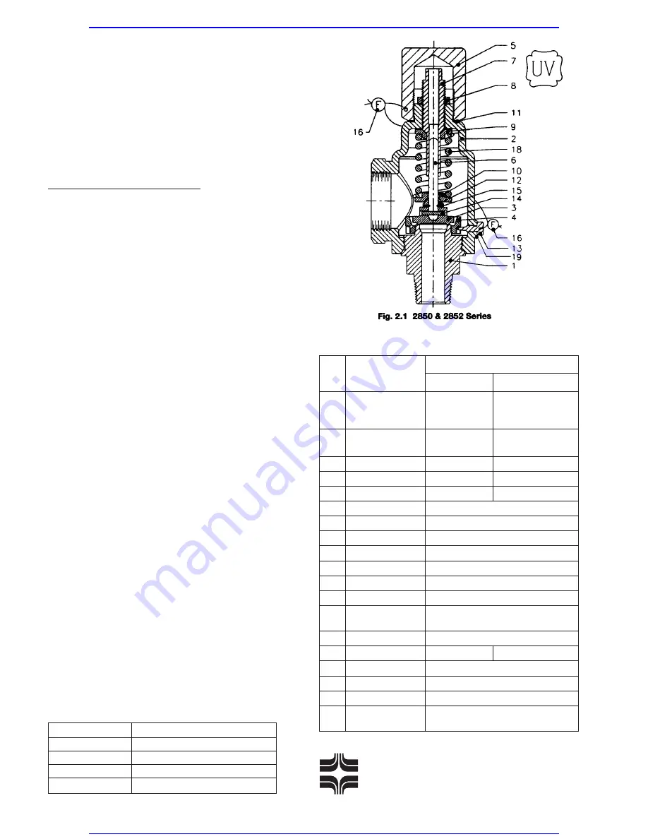
Series 2850 and 2852 (Fig. 2.1)
1. Mount valve vertically in a vise utilizing the flats
in the body.
2. Remove wire seal. Unscrew cap by turning
counterclockwise. Remove cap gasket. (For
open lever and packed lever cap construction,
refer to the section on Lifting Lever
Assemblies.)
3. Measure the distance from the top of the spring
adjusting screw to the top of the bonnet. Use
this measurement when reassembling the valve
to approximately duplicate the original set
pressure.
4. Loosen the jam nut.
5. Relieve the spring compression by turning the
spring adjusting screw counterclockwise.
6. Remove blowdown ring lock screw and gasket.
7. Thread a pipe into the outlet and turn the bon-
net counterclockwise. Lift the bonnet off to
expose internal subassembly.
8. Remove the upper spring button, spring and
lower spring button from the stem.
9. Remove the stem shoulder. Stem shoulder ring
may be a one-piece clip or split rings. Be care-
ful during disassembly; split rings may fall free.
Current valves do not use a stem shoulder and
split ring. The stem shoulder is an integral part
of the stem.
10. Lift the stem with the disc attached. If desired,
remove the grooved pin and lift the stem from
the disc.
11. Unscrew the blowdown ring from the body.
12. Clean all parts and threaded surfaces thor-
oughly. Replace all gaskets. Lap the body
seat and disc surfaces. (See the section on
Lapping for details.)
Bill of Materials
2
Farris Engineering
Division of Cur tiss-Wright Flow Control Corporation
Item Part Name
Material
2850 & 2852 2850/S4 & 2852/S4
SA-479 Type 316
SA-479 Type 316
1
Body
St. St. or SA-351
St. St. or SA-351
Gr. CF8M St. St.
Gr. CF8M St. St.
SA-216 Gr. WCB
SA-351 Gr. CF8M
2
Bonnet
Carbon Steel
St. St.
3
Disc
316 St. St.
316 St. St.
4
Blowdown Ring
316 St. St.
316 St. St.
5
Cap
Carbon Steel
316 St. St.
6
Stem
316 St. St.
7
Spring Adj. Screw
316 St. St.
8
Jam Nut
316 St. St.
9
Upper Spring Button
316 St. St.
10
Lower Spring Button
316 St. St.
11
Cap Gasket
316 St. St.
12
Stem Shoulder
316 St. St.
13
Blowdown Ring
316 St. St.
Lockscrew
14
Grooved Pin
316 St. St.
15
Stem Shoulder Ring
St. St.
316 St. St.
16
Wire Seal
St. St. Wire/Lead Seal
17
Nameplate
(not shown)
Stainless Steel
18
Spring
See Spring Table
19
Blowdown Ring
316 St. St.
L/S Gasket
Valve No.
Spring Material
2850
316 Stainless Steel
2852
Chrome Alloy, Rust Proofed
2850/S4
316 Stainless Steel
2852/S4
Chrome Alloy, Nickel Plated
Spring Table
Visit www.boighill.com to request a quote.
Visit www.boighill.com to request a quote.


