background image

19

most suitable values.
However, if the image is not perfectly centralised it may prove
useful to request the system to repeat the input signal analysis
and image positioning, calling the automatic control procedu-
re from the AUTO button on the remote control or keypad. When
this procedure is called it is helpful to have a white or light
coloured background on the screen in the current picture.

FREQUENCY/PHASE

These adjustments, available for progressive signals and for
signals from PC, ensure correspondence  between the number
of pixels making up the signal and the number of pixels making
up the projected image.
These parameters do not normally require adjustment because
the system checks the input signal and automatically sets the
most suitable values.
However, if the image appears disturbed (loss of position within
the equidistant vertical bands or instability and lack of
sharpness on the narrow vertical lines) it may help to prompt

the system to repeat the input signal analysis and determination
of the best parameters by calling the automatic adjustment
procedure with the AUTO


key on the remote control or on the

keypad.
If the automatic procedure fails to have the required effect, enter
the frequency and phase values manually and approach the
screen sufficiently to observe the effects of the adjustments.

Y / C DELAY

In the case of Video and S-Video signals, it may be necessary
to correct horizontal colour misalignment within the projected
image. For a given video standard (e.g. PAL or NTSC) the stored
value does not normally require further fine-tuning, unless the
source or connection cable has changed.

POSITION

ASPECT

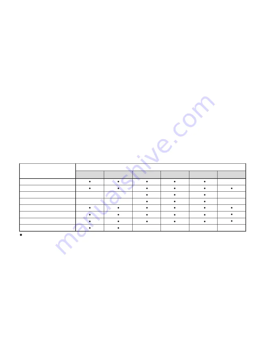
Video

S-Video

RGBS

YCrCb

Graphic RGB 

RGBS 15kHz

YCrCb 15kHz

ADJUSTEMENTS

INPUTS

FREQUENCY

-

-

-

-

-

PHASE

COLOR TEMPERATURE

GAMMA CORRECTION 

OVERSCAN

Y/C DELAY

-

-

-

-

-

-

-

Adjustable/can be set

Not adjustable/can not be set

DIGITAL INPUT 

TABLE 2   INPUT SIGNALS AND ADJUSTABLE/SETTING ITEMS

Summary of Contents for FDP-DLPHD20

Page 1: ...cod 46 0362 000 User and Installation Manual The home theater projector FDP DLPHD20 ...

Page 2: ...11 RGB YCrCb Input 11 Digital Input 12 Motorised projection screen output 12 RS232 interface connector 13 7 KEYBOARD PAD 13 8 REMOTE CONTROL 14 9 ON SCREEN MENUS 15 INDEX Source selection 15 Main menu 15 Picture 16 Image 18 Set up 20 Menu 21 Memories 23 Info 24 Quick menus 24 Messages 24 10 CLEANING AND MAINTENANCE 24 11 TROUBLESHOOTING GUIDE 25 12 OPTIONAL ACCESSORIES 26 A TECHNICAL SPECIFICATION...

Page 3: ...tes menu pages MEMORIES Activates Memories menu INFO Displays the selected source information and the projector status VCR Improves the video recorder signals quality ASPECT Selects image Aspect ratio SOURCE Displays the Source Selection menu BACK LIGHT Turn on the back light Up Down Left Right Arrow keys Navigate through and make adjustments to the On Screen menus Arrow Up Down activate Quick men...

Page 4: ...INPUT AUDIO OUT ZOOM CONTR OL RS 232 GRAPH ICS RGB R Cr G Y B Cb HV 1 2 4 3 5 ATTENTIO N pour ne pas comprome ttre la protection contre les resque d incende remplacer par un fusible de meme type et de mems caracteris tique CAUTION for continued protection against risk of fire replace only with same type and rating fuse ...

Page 5: ...ing been opened and the accumulated lamp operating hours may be slightly higher than the hours associ ated with the standard tests Fig 1 The FDP DLPHD20 incorporates patented Faroudja technology for deinterlacing color and detail processing including DCDi technology The result is that all sources are converted to very clean video signals full of detail and color while free of typical artifacts suc...

Page 6: ...ite video input 16 S Video input 17 VGA input 18 RGB YCrCb input 19 Digital Input 20 Optical Audio Output 21 12Vdc screen output 22 RS232 interface connector 6 4 1 2 3 5 8 DIGITAL INPUT AUDIO OUT ZOOM CONTROL RS 232 GRAPHICS RGB R Cr G Y B Cb HV 1 2 4 3 5 ATTENTION pour ne pas compromettre la protection contre les resque d incende remplacer par un fusible de meme type et de mems caracteristique CA...

Page 7: ...n reception which can be determinated by turning the equipment off and on the user is encuraged to try to correct the interference by one or more of the following measures Reorient or relocate the receiving antenna Increase the separation between the equipment and receiver Connect the equipment into an outlet on a circuit different from that to which the receiver is connected Consult the dealer or...

Page 8: ...Fig 4 Do not switch on your projector when flammable liquids or fumes are present Do not pour or drop fluids in the vents Do not use the projector when the room temperature is above 35 C 95 F AUDIO OUT pas compromettre resque d incende e de meme type tique ed protection against 250 V T 3 15A H 2 3 4 1 Fig 4 Do not obstruct the cooling air inlets on the top cover or the air outlets underneath the p...

Page 9: ...anual Fig 5 Do not touch the surface of the projection lens The projector must be positioned on a stable suitable platform or be installed using a bracket for fixed ceiling or wall installation Do not rest the projector on the side panels or on the rear panel when in operation Take care to position cables safely especially in dark places in order to avoid a trip hazard For installations using a ce...

Page 10: ...ting See Appendix C Projection distances for more information Use the motorised lens zoom to adjust the image size and the motorised lens focus to achieve maximum clarity With optimum focus you should be able to clearly see each single pixel when within close proximity to the screen Fig 7 FOCUS FOCUS FOCUS FOCUS DIGITAL INPUT AUDIO OUT ZOOM CONTROL RS 232 GRAPHIC S RGB R Cr G Y B Cb HV 1 2 4 3 5 A...

Page 11: ...incende remplace r par un fusible de meme type et de mems caracteris tique CAUTION for continued protection against risk of fire replace only with same type and rating fuse Fig 11 The output is activated Voltage 12 Vdc when the projector is switched on and is de activated no Voltage output when the projector is in stand by mode Some manufacturers offer screen masking systems to help fra me the pro...

Page 12: ...g Fig 13 Upon switch on in position I the projector will initialise red and green LEDs on Followed by stand by mode red LED on Fig 14 DIGITAL INPUT AUDIO OUT OOM CONTROL RS 232 GRAPHICS RGB R Cr G Y B Cb HV 2 4 3 5 ATTENTION pour ne pas compromettre la protection contre les resque d incende remplacer par un fusible de meme type et de mems caracteristique CAUTION for continued protection against ri...

Page 13: ...ow these simple steps With exception of coaxial RCA Phono type connectors always double check that the plug is inserted the correct way round to avoid damaging the plugs or the sockets on the projector Fig 16 DIGITAL INPUT AUDIO OUT ZOOM CONTROL RS 232 GRAPHICS RGB R Cr G Y B Cb HV 1 2 4 3 5 la protec remplacer par un u et de mems caracteristique CAUTION for continued protection against risk of fi...

Page 14: ...ignals can also have H V Composite Sync In this case connect the R G B or Y Cr Cb outputs of the source to the respective R Cr G Y B Cb inputs of the projector paying attention not to invert the positions and the synchroni sation signal to the HV input When connecting the three sets of RCA connectors use the colours as a guide connector R is COMPOSITE VIDEO INPUT CONTROL RS 232 B Cb HV 1 2 CVBS CO...

Page 15: ...igital images supported by multi channel digital audio and by control data Fig 21a The internal data elaboration by the projector divides the video data from audio data The audio data is available through a TOSLINK connector for fiber optic output Fig 21b MOTORISED PROJECTION SCREEN OUTPUT ZOO CONTROL RS 232 1 2 4 Fig 22 The projector is equipped with two outputs Voltage 12 Vdc for motorised proje...

Page 16: ...Selects Auto Adjust automatic optimisation of the displayed image Eight push buttons at the rear of the projector will allow com plete operation without the use of the remote control DIGITAL INPUT AUDIO OUT ZOOM CONTROL RS 232 GRAPHICS RGB R Cr G Y B Cb HV 1 2 4 3 5 CAUTIO risk of fire replace only with same type and rating fuse Fig 23 RS232 INTERFACE CONNECTOR It is possible to control the projec...

Page 17: ...e remote control sends commands to the projector via infrared signals It is possible to control the projector by pointing the remote control at the screen the sensor at the front of the projector will pick up the reflected infrared commands Fig 25 F1 ZOOM LIGHT DIGITAL INPUT AUDIO OUT ZOOM CONTROL RS 232 GRAPHICS RGB R Cr G Y B Cb HV 1 2 4 3 5 ATTENTION pour ne pas compromettre la protection contr...

Page 18: ... Inputs 1 VIDEO 2 S VIDEO 4 GRAPHICS RGB 5 1 2 3 4 5 15kHz RGBS RGBS 15kHz RGBS YCrCb 15kHz YCrCb 3 COMPONENT RGBS DIGITAL INPUT in the box additional information is displayed concerning the video standard for video signals or resolution for graphic signals and format Fom the SETUP menu it is possible to choose to visualize or not this information for more details check the SOURCE INFORMATION in M...

Page 19: ...as To ensure correct adjustment it may prove useful to display the signal relative to the grey scale within which the white level and the level immediately below it must be separately identifiable Alternatively use a scene composed of well lit white objects surrounded by light coloured objects with lower level lighting COLOR This control also called Saturation increases or decreases the picture co...

Page 20: ...ht part the filter is activated This allows you to compare the effect of the filter It is possible to deactivated the filter NOT ACTIVE to use the automatic adjustments AUTO or to manually select MANUAL the value suitable for the image with the VALUE adjustment In case of using the VALUE adjustement it is enoght to select to cursor below and set the value with the keys of the remote control Associ...

Page 21: ... reframe the screen to a variety of aspect ratios and screen size using an appropriate screen masking inter face connected to the 12 V output socket please refer to the screen manufacture s manual COLOR TEMPERATURE Changes the colour balance of the image Colours can be adjusted towards the red end of the spectrum low colour temperature values expressed in degrees Kelvin or the blue end high values...

Page 22: ...nds or instability and lack of sharpness on the narrow vertical lines it may help to prompt the system to repeat the input signal analysis and determination of the best parameters by calling the automatic adjustment procedure with the AUTO key on the remote control or on the keypad If the automatic procedure fails to have the required effect enter the frequency and phase values manually and approa...

Page 23: ...ens shift adjustment allows the projected image to be moved vertically up or down in relation to the centre of the screen the maximum adjustment being equal to half the height of the image in either direction Fig 31 DIGITAL INPUT AUDIO OUT ZOOM CONTROL RS 232 GRAPHICS RGB R Cr G Y B Cb HV 1 2 4 3 5 ATTENTION pour ne pas compromettre la protection contre les resque d incende remplacer par un fusibl...

Page 24: ...inputs are not utilized it is often helpful to blank them from the input list accessed with the 0 key Once the input has been chosen in the drop menu that appears by pressing the key it is possible to activate the source Fig 33 The exclusion or activation of the source will automatically renumber the remaining active inputs 2 S VIDEO 4 GRAPHICS RGB 5 DIGITAL INPUT DIGITAL INPUT 1 VIDEO 1 2 3 COMP ...

Page 25: ...nu English Zoom Focus Magnification Blank Color temperature Gamma correction F1 F2 Fig 35 Zoom Allows to access the optic zoom where the and keys allow to increase or decrease the size of the projected image Focus Once selected the and keys allow to focus the image Magnification Allows you to select the area to be viewed and then magnify the projected image The degree of enlargement is selected in...

Page 26: ...t the option Save current settings To confirm that the operation has been completed successfully the message Current set tings saved in Memory 1 is displayed at the bottom of the screen and the letter S appears to the left of the memory name The same procedure is used to save parameters in Memories 2 and 3 0 Auto 3 S MEMORIA 1 Memories Save current settings Save initial settings Rename 2 I 1 S Fig...

Page 27: ...any Memories selected the penultimate time the Memories page was accessed Memory 0 AUTO can be used even when you do not wish to enable the Memories management function for the signal currently in use Once Memory 0 has been selected when a source is chosen the settings that were effective at the time the Memory was previously recalled will be automatically applied INFO Displays the current status ...

Page 28: ...various sources If the signal source is a terrestrial broadcast via a VCR check that the receiving channel has been correctly tuned in and that the aerial system is in good working order Should the problem be present with a signal coming from a video recorder ensure that the videotape is an Original first generation copy and in good condition Adjust the VCR s tracking control for optimum picture p...

Page 29: ...olour misalignment on vertical details Verify compatibility of video graphic signals with technical specifications of your projector Adjust Y C Delay settings in the Image Adjustments Advanced Settings to reduce colour misalignment For best results use an external colour bar test pattern source Remote control does not work Check the batteries and for correct polarity Ensure that the area between t...

Page 30: ...alue measured in the laboratory under optimal condi tions it can be sensibly reduced by the unit misusing ELECTRICAL Input Signals CVBS on RCA Phono type connector S VHS on Mini DIN connector RGBHV on DB15HD connector RGBS YCrCb on RCA Phono type connector Digital Input Horizontal frequency from 15 to 80 kHz up to to UXGA format 60 Hz Vertical frequency 48 100 Hz Video standards automatically sele...

Page 31: ...4 LxHxD double reinforced carton expandable anti shock packaging gross weight including accessories 8 kg 17 7 lbs recyclable packaging material ENVIROMENTAL Operation temperature 0 to 35 C 32 to 95 F Transportation temp 10 to 55 C 14 to 131 F Storage temperature 10 to 55 C 14 to 131 F Humidity 10 to 90 relative humidity non condensing Safety EN 60950 UL 60950 Transportability desktop equipment Ele...

Page 32: ...creen size The manual lens shift adjustments allows the projected image to be moved vertically up or down in relation to the centre of the screen Fig 37b If the distance H between the centre of the screen and the centre of the lens exceed Hmax it is necessary to tilt the projector and use the digital keystone to correct the image projected Fig 37b Fig 37a H H L L 74 2 15 16 352 13 7 8 174 6 7 8 10...

Page 33: ...39 11 50 60 70 80 90 100 120 150 180 200 220 250 in m ft in Screen Screen size width diagonal min L Hmax max L Hmax Min projection distance 16 9 2 7 9 0 3 3 10 9 3 8 12 7 4 4 14 4 4 9 16 2 5 5 17 11 6 6 21 7 8 2 26 11 9 9 32 4 11 0 35 11 12 0 39 6 13 7 44 11 Max projection distance 1 1 44 1 3 52 1 6 61 1 8 70 2 0 78 2 2 87 2 7 105 3 3 131 4 0 157 4 4 174 4 9 192 5 5 218 m in m ft in m ft in 0 3 0 ...

Page 34: ...arpness Sharpness Mode Brightness Contrast Color Tint Sharpness Sharpness Mode Brightness Contrast Color Sharpness Filter Cinema Mode Video Type Noise reduction Noise reduction Video S Video PAL SECAM Aspect Color Temperature Gamma Correction Overscan Digital Input Aspect Color Temperature Gamma Correction Overscan Position Y C Delay Aspect Color Temperature Gamma Correction Overscan Position Aspe...

Page 35: ... OSD Position OSD Timeout Menu Zoom Focus Magnification Blank Color temperature Gamma correction Yes No Italiano English Français Español Deusch Português F1 F2 Active Yes No Name Cancel Confirm Edit source name 1 ABC 2 DEF 3 GHI 4 JKL 5 MNO 6 PQRS 7 TUV 8 0 WXYZ 9 _ _ _ _ _ _ _ _ _ _ _ 2 S VIDEO 4 GRAPHICS RGB 3 COMPONENT RGBS 1 VIDEO 1 2 3 4 S VIDEO 2 GRAPH RGB 4 COMP RGB 3 VIDEO 1 5 5 DIGITAL I...

Page 36: ...Cancel Confirm Edit memory name 1 ABC 2 DEF 3 GHI 4 JKL 5 MNO 6 PQRS 7 TUV 8 0 WXYZ 9 _ _ _ _ _ _ _ _ _ _ _ 0 Auto 3 S MEMORY 3 Memories 2 S MEMORY 2 1 S MEMORY 1 Save current settings Save initial settings Rename ...

Page 37: ...35 ...

Page 38: ...750 Palomar Avenue Sunnyvale CA 94085 Phone 408 735 1492 Fax 408 735 1571e www faroudja com ...

Reviews: