background image

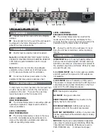
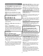
DIRECTIONAL BUTTONS:

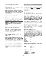
 Press [MENU] to access

the OSD.  Press again to deactivate. Use the DIREC-

TIONAL keys to navigate through the OSD options.

NOTE #1:

 To move to different OSD menu pages,

press [MENU], then [UP/DOWN] until the top triangle

turns yellow, then [RIGHT/LEFT]. A new MENU page

will appear as they are selected.

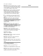
PROFILE BUTTON:

 Press to recall Profiles that have

been stored in the unit.

NOTE#1:

 After pressing the [PROFILE] button, then

quickly press a number button [1-8] to recall the

desired profile.


An alternative method is to press the [PROFILE]

button then use the [LEFT/RIGHT] buttons on the

remote to select the desired Profile on the OSD, then

press [STORE] to select.

STORE BUTTON:

 Press to store changes or selec-

tions when selecting the output scan rate or storing

and recalling Profile numbers. Profiles store 30

different image parameters.

STORING PRESETS USING THE OSD

1. Make all the desired image changes.

2. Using the DIRECTIONAL keys, go to the

INPUT menu.

3. Highlight the Profile number to store in.

4. Press the [STORE] button on the remote.


Profiles can also be stored in the SETUP menu.

Profiles stored using the OSD will override Profiles

stored via the SETUP menu AND visa-versa.

IMAGE ADJUSTMENTS:

 Adjusting picture levels

can be done by pressing a direct access button such

as [CONTRAST] and then pressing a three digit

number on the NUMBER PAD or by using the OSD

and directional arrows to move the adjustment

sliders on the OSD.

NOTE #1:

 It is recommended that Brightness and

Contrast be adjusted in the display device first, if

possible, then adjust for individual movies or chan-

nels using the DVP1080.

NOTE #2:

 A properly adjusted image is key to a

good  picture. For each installation, the processor

should be calibrated for the sources using reference

test patterns whenever possible. The following

section will list a suggested test pattern to use to get

the best results.

15

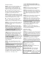
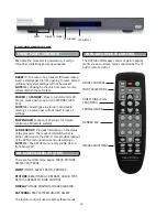
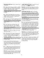
ON / OFF CONTROL:

 Press the [GREEN] button to

turn on the unit, press the [RED] button to enter the

standby mode.

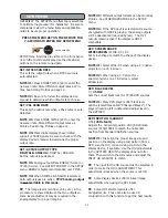
INPUT SELECT:

 Press the desired button to have

direct access to the different inputs.

NOTE #1:

 Press the [DVI/RGB] button to toggle

between the digital DVI input and the analog RGB

inputs.

Direct access IR commands are:

Press [DVI/RGB]+[0] = DVI

Press [DVI/RGB]+[1] = RGB.

NOTE #2:

 The [PASS/TX] button selects the PASS-

THROUGH input. Transcoding (TX) is not available

with the DVP1080

NOTE #3: 

The 

[DVD] button is not active

 with

this processor

NOTE #4 - PASSTHROUGH:

  When PASS-

THROUGH is selected, sources connected to the DVI

input will be sent to the DVI output unchanged by

the processor. Analog sources connected to the D15

input will be sent to the analog outputs unchanged

by the processor.

PASSTHROUGH=

DIGITAL (DVI) DIGITAL(DVI)
ANALOG RGBHV (D15)  RGBHV (BNC&D15)
YPrPb (BNC&D15)  YPrPb (BNC&D15)


An alternative approach is to select the input

using the On-Screen-Display: Press [MENU]


+ select

INPUTS


+ use the [LEFT / RIGHT]


directional buttons

to change inputs.


The SETUP menu has a setting for deactivating

unused inputs.  If an input is deactivated, it will not

be visible on the OSD, and the front panel LCD will

report INPUT NOT AVAILABLE if the direct access

button is pressed on the remote.

REMOTE BUTTON OPERATION

Summary of Contents for DVP 1080

Page 1: ...VICES PLEASE READ THIS COMPLETE MANUAL TO INSURE PROPER INSTALLATION AND OPERATION ANSWERS TO MOST TECHNICAL QUESTIONS CAN BE FOUND HERE INSTALLERS PLEASE REVIEW THIS MANUAL BEFORE CONTACTING FAROUDJA TECHNICAL SUPPORT PRODUCT OWNERS PLEASE CONTACT YOUR AUTHORIZED FAROUDJA DEALER FOR PRODUCT OR INSTALLATION QUESTIONS F F F F FAR AR AR AR AROUD OUD OUD OUD OUDJA JA JA JA JA ...

Page 2: ......

Page 3: ...451 5 237 414 A Division of Genesis Microchip Corp Made in USA QUICK START INSTALLATION GUIDE 4 5 SAFETY STATEMENT AND GUIDANCE 6 7 INSTALLATION AND CONNECTIONS 8 10 UNPACKING 8 MOUNTING 8 SETUP MENU 11 13 OPERATION INSTRUCTIONS 14 17 FRONT PANEL 14 INFRARED REMOTE AND ON SCREEN DISPLAY 14 16 RS232 COMMANDS 17 19 SPECIFICATIONS 20 WARRANTY 21 Please review the installation and operations instructi...

Page 4: ...ing Double check all projector screen calculations for best performance Avoid using keystone correction if possible 2 Connect Sources Make sure source devices are set to output the correct signal type that matches the installation Digital vs Analog YPrPb vs S video etc 3 Connect display Make sure display device is set for the correct input signal type Review the display s scan rate table found in ...

Page 5: ...FACTORY PRESS STORE 5 ON SCREEN DISPLAY INPUT INPUT ASPECT RATIO PROFILE RECALL PROFILE STORE PICTURE BRIGHTNESS CONTRAST COLOR TINT DETAIL ADVANCED COLOR DISPLAY H POSITION V POSITION BLANKING LEVEL L R BLANKING T B BLANKING PATTERNS TEST PATTERNS PATTERN SELECT SETUP MENU Default Setting in Bold SET NTSC SCAN RATE ADJUSTABLE 720P DEFAULT SET PAL SCAN RATE ADJUSTABLE 576P DEFAULT SET ACTIVE OUTPU...

Page 6: ... before cleaning Do not use liquid cleaners or aerosol cleaners Use a damp cloth for cleaning Do not use attachments not recommended by the product manufacturer as they may be hazardous Do not use this product near water Do not use immediately after moving from a low temperature to high temperature as this causes condensation which may result in fire electric shock or other hazards Do not place th...

Page 7: ...ing other products such as VCR s and personal computers you should turn off the power of this product for protection against electric shock Use only the accessory cord designed for this product to prevent shock The power supply voltage rating of this product is AC 120 V 220V the power cord attached conforms to the 120V power supply voltage Use only the power cord designated by our dealer to ensure...

Page 8: ...nued next page 2 5 6 9 NOT ACTIVE 10 1 3 4 7 8 11 12 8 LEVEL 3 WARNING EXCESSIVE TEMPERATURE The internal temperature has reached the maximum limit This warning will display for five seconds then the unit will shut down and cannot be powered up by the Power button or Remote Unplug the unit from the wall power to reset Once the unit has cooled down normal operation returns MOUNTING UNPACKING Shelf ...

Page 9: ...quence This connection can be programmed for on off operation in the SETUP menu or via RS232 12V 100mA Max 3 5mm 2 pin connector Tip 12V Sleeve Gnd 7 D15F COMPUTER PASS THRU INPUT Use with high scan rate analog signals to pass through to the display device NOTE 1 Signals connected to this input are not processed or transcoded YPrPb to RGBHV NOTE 2 Analog cables must be connected from the processor...

Page 10: ...stem interface NOTE 1 The SETUP menu offers selections for RS232 operation See Page 11 for details 11 RGBHV YPrPb ANALOG OUTPUTS For use with high scan rate analog displays NOTE 1 If a HDCP encrypted DVI source is selected the analog outputs are deactivated by law In this case the front panel LCD will display ENCRYPTED SOURCE ANALOG OUT DISABLED NOTE 2 RGBHV 5 wire is highly recommended to use ove...

Page 11: ...VD sources NOTE 1 Many DVD players offer black level options sometimes called Enhanced Blacks The player should be left in default and adjust level in the DVP1080 SET INPUT HD H ADJUST 0 50 25 Default Adjusts the horizontal position of High Definition sources 720p 1080i to match the horizontal position from Standard Definition sources NOTE 1 First align the proper image size and position on the di...

Page 12: ... composite sync on the H connector when using analog RGB output 4 wire connection Note 1 This option defaults to AUTO and is locked when YPrPb output is selected RGBHV is recommended for best results INPUT ENABLE DISABLE Each input can be enabled or disabled depending on the installation Deactivating unused inputs helps to streamline operation Each input is listed in the SETUP menu for control VID...

Page 13: ...ILE NUMBER THEN PRESS STORE 3 PROFILES CAN BE RECALLED USING THE REMOTE CONTROL AND THE OSD Profiles can be recalled with the IR remote using the OSD or via RS232 Profiles can also be stored using the OSD which will over write Profiles stored here and vis versa SET STORE PAL PROFILE STORE PROFILE 1 8 Stores all current settings for PAL sources 30 differ ent parameters to the preset number selected...

Page 14: ...ame task POWER STANDBY Press to turn ON unit LED Green press again to put unit in STANDBY LED Red NOTE 1 All settings are stored in nonvolatile memory so a power loss will not result in loss of settings IR WINDOW Location of IR sensor for remote control and IR remote systems LCD READOUT Provides information on the status of the processor The readout will match what is being controlled via the OSD ...

Page 15: ...ontrast be adjusted in the display device first if possible then adjust for individual movies or chan nels using the DVP1080 NOTE 2 A properly adjusted image is key to a good picture For each installation the processor should be calibrated for the sources using reference test patterns whenever possible The following section will list a suggested test pattern to use to get the best results 15 ON OF...

Page 16: ... reducing the detail level can help to make the artifact less visible NOTE 3 Suggested test pattern DVD movie with a close up of a face in still frame Adjust so the face has detail but the edges do not look fake such as along the brdige of the nose ASPECT RATIO BUTTONS Each selects the proper aspect ratio of the source being viewed NOTE 1 The proper screen shape must be set in the SETUP menu durin...

Page 17: ...ayer and patterns from the satellite box if available This way the final image is adjusted for the complete signal path from source throught the processor to the display 17 RS 232 INSTRUCTIONS The DVP Header followed by a comma no space is used to delimit the Header from the Command The following is an example using Windows HyperTerminal for Power On using a standard Modem Cable dvp on Enter Enter...

Page 18: ... 50 default Tint V Video Input X YCrCb Input Y S Video Input SETUP COMMANDS BB 0 100 Bottom Blanking BL 0 100 Border Curtain Level black to white BLT 6 255 LCD Backlite Timer on front panel BLV 0 0IRE 1 7 5 IRE BLACK LEVEL CR 0 0 255 1 16 235 DVI INPUT LEVEL CS 1 On 0 OFF Composite Sync for RGB output DHS 0 NORMAL 1 WIDE DVI INPUT H SYNC DVID DVI Input Disabled DVIE DVI Enabled E 1 On 0 OFF RS 232...

Page 19: ...ed NTSC SCAN RATES SRN1 1400X788 SRN2 1920 x 540 SRN3 800X600 SRN4 1280 x 720 SRN5 1024 x 768 SRN6 1280 x 768 SRN7 1366 x 768 SRN8 1440 x 960 SRN9 1280 X 1024 SRN10 DILA SRN11 1400 x 1050 DILA3 SRN12 1920 x 1080 PAL SCAN RATES SRP1 720x576 50Hz SRP2 720x576 100Hz SRP3 1280x720 50Hz SRP4 1024x768 75Hz SRP5 1024x768 100Hz SRP6 1920x1080 50Hz TEST PATTERN HELP MENU TPHELP TEST PATTERN HELP MENU TP0 T...

Page 20: ...Comp Sync 1v pp 480i 480p 720p 1080i RGB 700mv pp HD PC Pass Thru D15M DVI Input DVI I female Digital Only 0 255 16 235 Outputs Progressive RGBHV 700mv pp TTL Sync H V Sync 2 5v pp 75ohm min YPrPb 700mv pp Sync on Y 1v pp RGsB Gs 1v pp RGB 700mv pp Digital Video Interface DVI I female digital only 0 255 HDCP Complient Operational Temperature Range 41 F to 104 F 5 C to 40 C with internal tempuratur...

Page 21: ...a Service in the original shipping carton Should a product fail to conform to the warranty above then Faroudja shall at Faroudja s sole option i repair the non conforming product or portion thereof provided that the product is returned to Faroudja within the warranty period in accordance with the return procedures set forth above or ii provide Purchaser with replacement for the nonconforming produ...

Page 22: ...faroudja Rev 1 3 05 ...

Reviews: