Faro ACCSS8031 Installation Manual Download Page 6

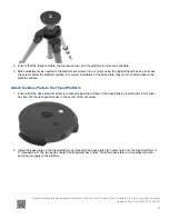
• Extend the tripod as little as possible. Less height

means more accuracy.

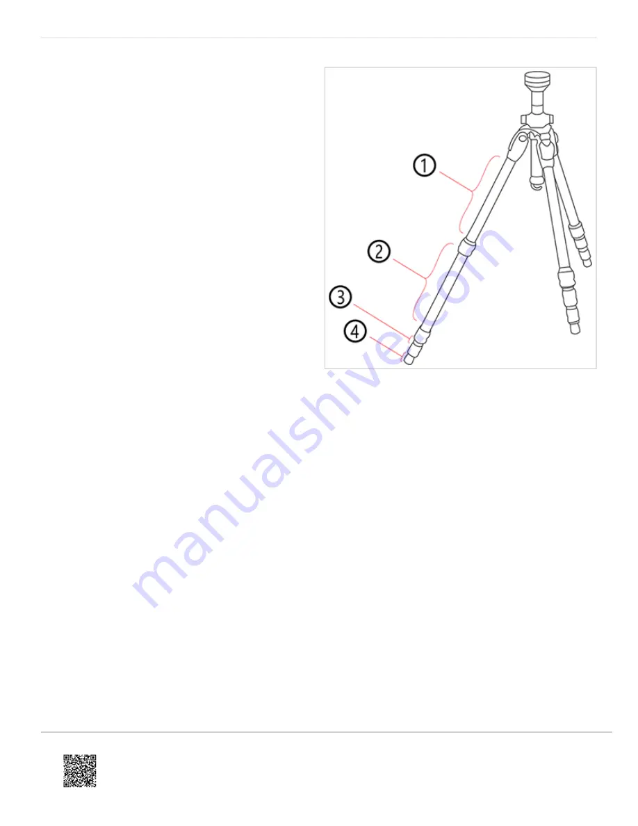
• Extend the thicker segments of the legs before the

thinner.

• You can extend a leg segment partially, if necessary,

to achieve a specific height, but do not partially extend
several segments of the same leg.

• The tripod has four leg segments, three of which are

extendable. Fully extend segment 

, leaving

segments 

 and 

 collapsed. This results in a

working height of approximately 130 cm (51.2 in).

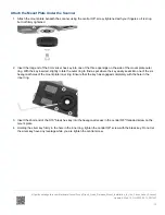
• The tripod is equipped with large, adjustable rubber

feet. Each time you move the tripod, ensure that the
feet are correctly resting on the ground. If you need to
place the tripod on unstable ground (e.g., grass,
gravel, mud), use the supplied spikes instead of the
rubber feet. Press the spikes individually into the
ground until they reach a stable, load-bearing layer.

• After you set the tripod on the ground, check the leg

latches. If any latches are loose, spread the legs
slightly until the latches cannot be wiggled. This
ensures that the tripod is firmly planted on the ground,
and unlikely to shake or vibrate during scanning.

• The use of the center column significantly reduces the rigidity of the tripod. We recommend that you avoid using the

center column. If you need higher working heights, we recommend using a larger tripod. Make sure that a such a
tripod is also stable.

• For scans close to the ground, slide all leg segments into each other before setting the leg angle to flat. The rubber

feet have a recess that helps to achieve full-surface contact, even with a flat leg angle. To do this, turn the feet
individually by hand.

• Ensure that the twist-lock sleeves for leg length adjustment, the central wing nut of the tripod shoulder, and the

tripod head are always tightly screwed together.

• To achieve a better grip on hard surfaces, slightly tension the tripod legs before starting a scan. Tension the legs by

holding two of the three tripod legs as close to the ground as possible with your hands, pulling them slightly apart
from each other and away from the third leg, then pressing them into the ground.

Windy Conditions

FARO recommends the use of the ACCSS8032 tripod (with the Focus scanner) in winds less than 35mph (56km/h). In
stronger winds, it may be required to use a heavier aftermarket surveyor type tripod. See the following guidelines to
maximize stability of your FARO tripod in windy conditions.

• Use sandbags to stabilize each foot of the tripod. You can also stretch a rope or shock cord between the tripod’s

center hook and a weight (max. 20kg), switchable magnetic base, or existing anchor point (max. force 200N).

• Orient one of the tripod legs with the main wind direction. Also, only extend one section of the tripod legs (never

extend the center column – this degrades the resistance against vibrations).

https://knowledge.faro.com/Hardware/Focus/Focus/Tripod_Quick_Release_Mount_Installation_for_the_Focus_Laser_Scanner

Updated: Wed, 12 Oct 2022 22:14:00 GMT

6

Summary of Contents for ACCSS8031

Page 1: ... FARO Part ACCSS8031 comes with the following components 1 x Part A Scanner Mount Focus 1 x Part B Coupling with int 5 8 thread 1 x Part C Base Plate w Graduated Dial 1 x Part D Thread Adapter 5 8 to 3 8 shipped pre installed into Part B 1 x Hex Key 4 mm Attach the Scanner Mount to the Bottom of the Scanner 1 Verify that all four hooks on the Scanner Mount A are in their fully retracted position I...

Page 2: ...t are secure and the platform is as level as possible 3 Remove any previously installed adapters or mounting plates Attach the Base Plate to the Tripod Platform 1 Verify the mounting stud of the tripod is a 3 8 thread If the mounting stud is a 5 8 thread the Thread Adapter D should be removed from the Coupling B using the provided 4mm hex key 2 Place and center the Base Plate w Graduated Dial C on...

Page 3: ...securely attached to the tripod platform Attach Base Plate to Tripod ACCSS8032 1 Before attaching the mount to the tripod baseplate remove the protective covering from the tripod baseplate screw https knowledge faro com Hardware Focus Focus Tripod_Quick_Release_Mount_Installation_for_the_Focus_Laser_Scanner Updated Wed 12 Oct 2022 22 14 00 GMT 3 ...

Page 4: ...2 Holding the scanner above the tripod lower the scanner onto the tripod over the Coupling B 3 Rotate the scanner to orient it relative to the location you want to scan 4 Tighten the thumbscrew until the scanner is securely locked onto the tripod https knowledge faro com Hardware Focus Focus Tripod_Quick_Release_Mount_Installation_for_the_Focus_Laser_Scanner Updated Wed 12 Oct 2022 22 14 00 GMT 4 ...

Page 5: ... you are setting up the tripod on a natural surface replace the rubber tripod feet with spikes for increased stability 2 Periodically check the tightness of the quick release on the tripod 3 Never force the laser scanner to turn without releasing the thumb screw 4 Remove the laser scanner before moving the tripod To Achieve Stability and Rigidity https knowledge faro com Hardware Focus Focus Tripo...

Page 6: ... slide all leg segments into each other before setting the leg angle to flat The rubber feet have a recess that helps to achieve full surface contact even with a flat leg angle To do this turn the feet individually by hand Ensure that the twist lock sleeves for leg length adjustment the central wing nut of the tripod shoulder and the tripod head are always tightly screwed together To achieve a bet...

Page 7: ... to lock the legs in wider horizontal position but this will dramatically limit the scanner height and make the setup less resistant against vibration https knowledge faro com Hardware Focus Focus Tripod_Quick_Release_Mount_Installation_for_the_Focus_Laser_Scanner Updated Wed 12 Oct 2022 22 14 00 GMT 7 ...

Page 8: ...r Scanner Quick Release package FARO Part ACCSS8008 Supported Hardware FARO FocusM 70 FARO FocusS 70 FARO FocusS 150 FARO FocusS 350 Media iframe embed and object tags are not supported inside of a PDF https knowledge faro com Hardware Focus Focus Tripod_Quick_Release_Mount_Installation_for_the_Focus_Laser_Scanner Updated Wed 12 Oct 2022 22 14 00 GMT 8 ...

Page 9: ... the scanner item 2 in the picture Note Part a and b are attached together when you receive the package Rotate the Mount Plate to separate the two parts c 1 Imperial 3 16 Hex Key depicted in these pictures as black in color d 1 Metric 3 mm Hex Key depicted n these picture as silver in color 3 Retrieve the Tripod Hex Key from the original package Set Up the Tripod 1 Extend the legs of the tripod an...

Page 10: ...that the base plate set screw is recessed below the surface of the base plate by inserting the 3 mm silver hex key into the hexagonal recess in the center of the set screw 2 Install the base plate on the tripod platform by threading the base plate 3 8 center hole onto the tripod platform 3 8 threaded stud The two parts should fit flush against each other Twist the base plate in a clockwise directi...

Page 11: ...t screw using the 3 mm silver hex key inserted into the recess at the center of the set screw 5 Check that the base plate is securely attached to the tripod platform and is unable to spin in any direction https knowledge faro com Hardware Focus Focus Tripod_Quick_Release_Mount_Installation_for_the_Focus_Laser_Scanner Updated Wed 12 Oct 2022 22 14 00 GMT 11 ...

Page 12: ...of the six hexagonal holes of the mount plate inner ring Ensure that the key has engaged completely with the hole in the inner ring 3 Insert the short end of the 3 16 black hex key into the hexagonal recess in the central 3 8 threaded screw on the mount plate 4 Holding the silver key firmly in the hole in the inner ring tighten the central 3 8 screw with the black key Do not let the silver key hav...

Page 13: ...tripod base plate 2 Lower the scanner onto the base plate keeping the lock hole aligned with the corresponding circular indentation 3 With the scanner contacting the base plate turn the scanner to orient it relative to the location you want to scan 4 On the scanner mount plate rotate the outer ring until the scanner is securely locked onto the tripod https knowledge faro com Hardware Focus Focus T...

Page 14: ...eaving segments and collapsed This results in a working height of approximately 130 cm 51 2 in The tripod is equipped with large adjustable rubber feet Each time you move the tripod ensure that the feet are correctly resting on the ground If you need to place the tripod on unstable ground e g grass gravel mud use the supplied spikes instead of the rubber feet Press the spikes individually into the...

Page 15: ...e tripod s center hook and a weight switchable magnetic base or existing anchor point Troubleshooting When attempting the remove the scanner from the tripod in some instances the entire quick release assembly can begin to rotate making it impossible to separate the two quick release halves If this occurs 1 Continue rotating the outer ring clockwise to the right until the scanner and the complete q...

Page 16: ...unt assembly two black components and integrated precision washer with knob b 1 x Screw UNC 3 8x2 c 4 x Hex Screws M5x20 d 1 x Hex key 4mm e 1 x Hex key 5 16 f Optional 1 x Tribrach to 5 8 adapter 2 Remove the scanner from the transport case and lay the scanner on its side on a flat surface If you have a scanner transport cover you can install the Tribrach adapter with the scanner inside the cover...

Page 17: ...power inlet 4 Insert and tighten the four screws with the included hex wrench do not over tighten 5 To install the lower tripod mounting ring first remove the 5 8 inch screw from the tripod using reasonable torque https knowledge faro com Hardware Focus Focus Tripod_Quick_Release_Mount_Installation_for_the_Focus_Laser_Scanner Updated Wed 12 Oct 2022 22 14 00 GMT 17 ...

Page 18: ...rt the 5 8 inch screw and tighten until snug with the included hex wrench Make sure that the numbers on the tripod mounting ring are right side up 8 Once the tripod mounting ring is secure place the scanner on the tripod https knowledge faro com Hardware Focus Focus Tripod_Quick_Release_Mount_Installation_for_the_Focus_Laser_Scanner Updated Wed 12 Oct 2022 22 14 00 GMT 18 ...

Page 19: ... are ready to use the quick release with your tripod and Focus3D Troubleshooting If you cannot remove the screw in steps 5 and 6 do not apply excessive force as it may damage the tripod Instead contact FARO Support for instructions https knowledge faro com Hardware Focus Focus Tripod_Quick_Release_Mount_Installation_for_the_Focus_Laser_Scanner Updated Wed 12 Oct 2022 22 14 00 GMT 19 ...

Reviews: