1
Revision date: 09.21.18
113593
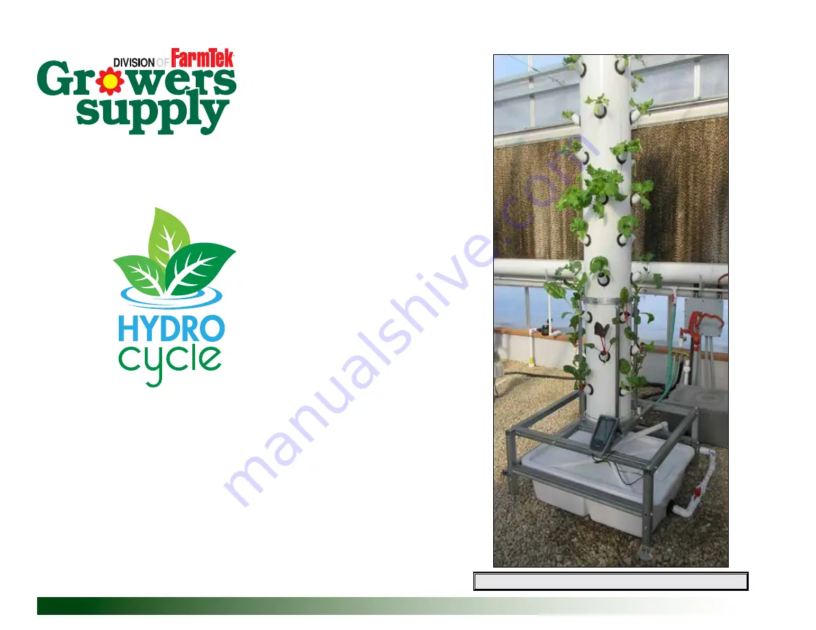
8' Vertical System (44 Grow Sites)
*Actual system may differ from system shown.
HydroCycle Vertical
Aeroponic Systems
©2018 Growers Supply
All Rights Reserved. Reproduction
is prohibited without permission.
Page 1: ...e 09 21 18 113593 8 Vertical System 44 Grow Sites Actual system may differ from system shown HydroCycle Vertical Aeroponic Systems 2018 Growers Supply All Rights Reserved Reproduction is prohibited without permission ...
Page 2: ...your system is important Check the following items periodically to properly maintain your aeroponic system Check connections to verify they remain tight Verify pump is working properly Check and clean filter to optimize performance Clean reservoir periodically to prevent unwanted contamination of solution Monitor temperatures room and solution to maximize plant growth SAFETY PRECAUTIONS Apply pvc ...
Page 3: ...Information PICTORIAL GUIDE Use the following graphics and photos to identify system parts 110077 Air Stone WF4065 WF1540 WF1390 112710 WF3375 WF3316 WF3420 112689 LJ2502 LJ2502 WF2190 WF4790 Key Punch WF1570 111045 WF2193 WF8582 113595 113696 ...
Page 4: ...pump without first priming it Doing so will damage the pump Consult all documentation included with the pump before you begin ATTENTION A timer is required to cycle the water pump on and off If you did not purchase a timer contact your sales representative to purchase the 112531 timer Timer not included Additional purchase required 112531 Timer WF6990 PVC Cement and 113372 Purple Primer PVC PRIMER...
Page 5: ...learance it will need 5 Consider where main power will connect to water pump and air pump ATTENTION All electrical wiring to be completed by an electrical contractor in accordance with established electrical codes 6 Depending on setting additional lighting may be required Ensure that electrical service can support the addition of artificial light fixtures if needed TIMER REQUIRED For best results ...
Page 6: ...to allow for fitting installation Actual tank may differ from the example shown 3 Attach WF8582 bulkhead to reservoir Hex nut and thin flat washer are outside the reservoir Install thick rubber washer on inside Tighten until snug using large adjustable pliers 4 Continue by preparing the cover for system assembly 1 DRILL RESERVOIR AND INSTALL BULKHEAD FITTING Assembly Instructions Reservoir Prepara...
Page 7: ...drill two 2 holes in the raised area on either side of the porthole for the air lines 4 Remove all debris from the cover and around all holes to prevent it from dropping into the reservoir when cover is set in place 5 Continue with the next procedure DRILL DRAIN AND AIR LINE HOLES IN COVER Drill 1 3 8 to 1 1 2 drain hole here Drill two 5 16 air tube holes in either location Photo shows prepared co...
Page 8: ...HE AIR PUMP AND AERATOR STONES Attach 110091 tube to air stone 110077 Air Stone 4 Plug pump into an outlet and check the stones to ensure air is pumping through them Place stones in a small container of water if needed to confirm operation 5 Turn off pump after checking the operation 6 Set the air pump on the cover or inside the reservoir until grow tube is installed 7 Continue with the next proce...
Page 9: ...595 grommet in each Carefully start grommet in hole and work it around until grommet is seated flush against lid Fit is tight 3 Flip lid over Verify that collar of grommet is flat against cap surface 4 Cut one 1 sixteen inch 16 drain extension from the 1 pvc tube 5 Install drain extension into either 10 cap Wet drain tube end for easier installation End of tube is flush with lip of rubber grommet ...
Page 10: ...onsult the procedure to replace damaged mist emitters near the back of this guide if needed 2 Seat cap tightly against shoulder of threaded fitting to seal against cap 3 Wrap threads of mist column fitting with thread tape Wrap in a direction that will not allow the tape to unwrap when manifold section is attached 4 Add the WF2190 fitting to the threaded end of mist column 5 Hold column with one h...
Page 11: ...d in place ATTENTION Do not cement cap to grow tube Tube must remain free to remove for system maintenance and cleaning 8 Look into grow tube through plant sites and verify that mist nozzles align with sites Adjust turn cap as needed and press back into place 9 Take cap with drain extension Procedure 4 and install on bottom of grow tube Seat in place with palm of your hand Do not cement 10 Set the...
Page 12: ...is assembled install all 111045 elbows Wet end of 111045 elbow and insert it into 112710 uniseal Install all elbows so open end points up and away from drain extension end of tube ATTENTION Seat elbow tight against uniseal to prevent leaks 111045 Verify all elbows are seated tight against seal STEP 1 STEP 3 STEP 2 STEP 4 Toward Top Toward Top ...
Page 13: ...pport ring in this manner 1 Remove two 2 lower 1 4 x 1 2 hex bolts to loosen two vertical supports 2 Remove two 2 1 4 x 1 bolts of upper supports 3 Lift upper support and two vertical supports assembly off main tower frame 4 Set cover on reservoir if needed and slide reservoir under tower frame 5 Slide grow tube drain extension through hole in cover and seat tower in place on frame ATTENTION Remov...
Page 14: ...nfirm water flow direction arrows on all valves and filters before assembly Dry fit assemblies before applying pvc primer and pvc cement to ensure desired result WF2193 Adapter WF2190 Adapter WF1033 112066 113696 Ball Valve 113696 Ball Valve WF1570 Elbow x2 Use short sections of 1 pvc tubing to connect elbows 113583 Pump 113696 Ball Valves ATTENTION Connect water pump to timer If needed contact yo...
Page 15: ...ng cycles noted on Page 5 ATTENTION Once system is running monitor plant growth and adjust watering cycles as needed to maximize results 12 System is ready to use Add plants and grow Mix nutrient solution according to plant needs and instructions included with nutrient General Cleaning and Maintenance Instructions For optimal performance and to increase yields check and clean reservoir periodicall...
Page 16: ...and Maintenance 1 Connect a garden hose to the 112066 shutoff valve on filter Place end of hose in a bucket or run it to desired location 2 Open shutoff valve to pump out reservoir Turn off pump once reservoir is empty To prevent damage do not run pump dry 3 Clean reservoir as needed and repeat steps to pump it out again Prime pump if needed Consult documentation included with pump Close shutoff v...
Page 17: ...SYSTEM FILTER ASSEMBLY IS THE SAME STEPS FOR CLEANING THE FILTER ARE THE SAME Clean Filter Screen and Housing 1 Turn off pump Open valve on filter to drain supply line and filter 2 Grip filter housing and main supply line and remove housing Do not apply force to filter or supply line fittings Hold these steady when disassembling filter 3 Remove screen from housing Using clean water rinse housing a...
Page 18: ...be Hold drill steady and drill slowly Do not damage threads or distort hole with bit 2 Take a replacement WF4065 mist emitter and start it in threaded hole Skip to Step 4 If you are unable to start mist emitter in threaded hole continue with next step 3 Clean threads using tap Secure round shaft of tap in drill chuck Tap should spin evenly with no visible wobble Do not bottom tap out in tube Run i...
Page 19: ...19 Revision date 09 21 18 113593 PAGE RESERVED FOR CUSTOMER NOTES AND RECORDS ...
Page 20: ... 100 14 FAG102B 8 HEX CAP 1 4X3 4 ZINC EACH 15 FAG336B 20 HEX CAP 5 16 X2 1 2 ZINC EACH 16 FAG340B 2 HEX CAP 5 16X3 1 2 ZINC EACH 17 FALB01B 8 NUT BULK 1 4 20 ZINC EA 18 FALB02B 2 NUT BULK 5 16 18 ZINC EA 19 FAME07B 22 BULK FLATWASH 5 16 ZINC EA 20 FALC30 8 COUPLING NUT 1 4 20 ZINC EA 22 113030S01 4 FLOAT TABLE AJUSTABLE FOOTER STY 1 23 FALB34B 4 NUT HOTDIP GLV 3 8 16 24 112477 4 FODDER FRAME LEVE...
Page 21: ...13 13 23 22 24 ANGLE CLIP TO SUPPORT RING FOOT INSERT ASSEMBLED VERTICAL SUPPORT TO SUPPORT RING SUPPORT RING ASSEMBLED LEG TO LOWER HORIZONTAL SUPPORTS LEG TO UPPER HORIZONTAL SUPPORTS 10 10 CENTERING TOWER ONTO STAND NOTE TOWER WILL BE TEK SCREWED TO BASE BEFORE BOLTS ARE TIGHTENED NOTE FOOT INSERT IS TEK SCREWED TO LEG NOTE TOWER WILL BE CENTERED ON BASE OF AEROTOWER STAND 25 25 ...