background image

11

GB

Revisione - 00 


Date 04-2017

KJ 70-A

WARNING!!! A WRONG ADJUSTMENT OF THE RIVETING TOOL STROKE 

MAY CAUSE A FAULTY CLAMPING OF INSERTS AND MAY BRAKE THE TIE ROD!

PLACING OF THE INSERT

Make sure that the couple tie-rod/head mounted on your riveting tool is suitable for the insert to clamp; otherwise, change size 
accordingly. Usually the riveting tool is supplied with the couple tie-rod/head corresponding to a 

3/8-16

 thread. Before using 

the riveting tool and after any change of size, perform the following operations according to the size and thickness of the part to 
clamp. Plug in the notchs of the regulation stroke ring nut the special key (issued). Adjust the riveting tool stroke to the minimum 
by turning the ring nut “

G

” to “

” marked on the tool. Place the insert on the tie rod and push slightly on it so as to make it clamp 

automatically. Make sure the insert head touches the riveting tool head properly. Fasten the insert and in order to ensure a proper 
clamping of the material, adjust the riveting tool stroke by turning the ring nut “

G

” accordingly. By increasing stroke, i.e. by turning 

the ring nut “

G

” to “

+

”, the distance “

h

” between head and insert deformation will decrease and clamping will result more effective.

+

H

H

G

Summary of Contents for KJ 70-A

Page 1: ...LI RIVETTATRICE OLEOPNEUMATICA PER INSERTI 6 32 1 2 13 ISTRUZIONI D USO PARTI DI RICAMBIO TRANSLATION OF ORIGINAL INSTRUCTIONS HYDROPNEUMATIC RIVETING TOOL FOR INSERTS 6 32 1 2 13 INSTRUCTIONS FOR USE...

Page 2: ...06 42 CE e successive modificazioni ed integrazioni La persona autorizzata a costituire il fascicolo tecnico risponde al nome di Massimo Generali presso la Far S r l con sede in Quarto Inferiore BO al...

Page 3: ...I I ISTRUZIONI D USO 4 INSTRUCTIONS FOR USE 9 PARTI DI RICAMBIO 14 SPARE PARTS 16 KJ 70 A GB GB...

Page 4: ...l attrezzo viene acquistatoattraversounrivenditoreautorizzatoesoloquando viene impiegato per gli usi per i quali stato concepito La garanzia non valida se l attrezzo non viene utilizzato e se non vie...

Page 5: ...one di esercizio 6 BAR Diametro interno minimo tubo alimentazione aria compressa 8 mm Consumo max aria libera per ciclo 10 4 Nl Forza massima 6 BAR 30143 N PESO Pistola 2 050 Kg Totale 6 850 Kg Temper...

Page 6: ...a serrare Inserire nelle tacche della ghiera di regolazione corsa I apposita chiave in dotazione Regolare la corsa della rivettatrice al minimo ruotando per quanto possibile la ghiera G nel senso indi...

Page 7: ...l interno in modo da sbloccare l innesto dal tirante Contemporaneamente svitare il tirante ed estrarlo leggermente FIG 3 4 Mantenendo sbloccato l innesto avvitare il formato di tirante desiderato Com...

Page 8: ...ico e ripristinarne la corretta quantit di olio Procedere quindi come segue Riporre il corpo rivettatrice all interno di un raccoglitore in modo da non disperdere eventuali fuoriuscite di olio e posiz...

Page 9: ...a 12 month warranty The tool warranty period starts on the date of delivery to the buyer as specified in the relevant document The warranty covers the user buyer provided that the tool is purchased t...

Page 10: ...psi Min int diam of the compressed air feeding hose 0 315 Air consumption per cycle 6 3 in Max power 87 psi 3070 lbf WEIGHT Gun 4 52 lb Total 15 lb Working temperature 23 F 122 F Root mean square in...

Page 11: ...erations according to the size and thickness of the part to clamp Plug in the notchs of the regulation stroke ring nut the special key issued Adjust the riveting tool stroke to the minimum by turning...

Page 12: ...ight pressure on the head inwards in order to dechuck the tie rod clutch at the same time unscrew the tie rod and extract it PICTURE 3 4 Keep the clutch dechucked and screw the tie rod size desired Wh...

Page 13: ...pletely free from air bubbles When the operation has been carried out replace the plug C and make sure that oil has reached the border of the threaded hole Screw the screw cap A and clean carefully th...

Page 14: ...9 1 Testina 3 8 16 UNC 3 8 24 UNF 16 710884 1 Ghiera 17 710880 1 Cannotto porta testina 18 710878 1 Raccordo anteriore 19 710881 1 Cannotto porta tirante 20A 710879 1 Innesto per tirante A 21A 710138...

Page 15: ...710829 1 Ammortizzatore D 23 711659 1 Stelo 24D 710923 1 Guarnizione OR 012 D 25 711678 1 Pistone pneumatico 26D 710912 1 Dado M 10 x 6 D 27 711679 1 Guarnizione OR 2 339 28 711655 1 Cilindro 29E 7118...

Page 16: ...rod 3 8 16 UNC 15 711109 1 Head 3 8 16 UNC 3 8 24 UNF 16 710884 1 Ring nut 17 710880 1 Sleeve carrying head 18 710878 1 Front connector 19 710881 1 Sleeve carrying tie rod 20A 710879 1 Tie rod clutch...

Page 17: ...ing 11 UNI 7437 44 710922 2 Gasket OR 018 45 712268 1 Spring guide plug 46 711665 1 Valve cap 47 711085 1 Silencer SPL 3 8 48 711068 2 Connector 6520 5 1 8 49 711826 1 Connector 2020 1 4 50 711121 1 R...

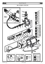
Page 18: ...6 17 18 19 20 A 21 A 1 72 3 4 85 7 8 9 10 12 11 30 31 37 36 34 33 22 A 23 24 25 26 83 83 A A B B 27 38 B 39 B 28 29 78 77 30 31 37 35 73 44 43 59 46 45 34 32 74 75 76 13 14 61 62 63 64 65 47 48 49 50...

Page 19: ...25 26 D 27 28 18 C 19 20 2 3 8 9 10 4 5 6 7 24 D 29 E 33 34 F 35 F 30 31 E 32 36 F 35 F 36 F 35 F 36 F 37 F 38 40 41 39 42 43 44 45 44 46 KIT C KIT D KIT E KIT F 16C x1 17C x1 18C x1 22D x1 26D x1 24...

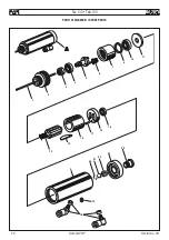
Page 20: ...20 PARTI DI RICAMBIO SPARE PARTS KJ 70 A Date 04 2017 Revisione 00 1 13 9 18 19 20 21 22 24 23 12 14 17 15 16 2 4 5 3 6 7 8 10 11 Tav 3 3 Tab 3 3...

Page 21: ......

Page 22: ...KJ 70 A...

Page 23: ......

Page 24: ...ww far bo it Organisation La lista de los servicios postventa es disponible en nuestro sitio web http www far bo it Organizaci n Listapunkt wserwisowychjestdost pnananaszejstronieinternetowej http www...

Reviews: