background image


ЗАПЧАСТИ • SPARE PARTS


F002


7


6


5


4


3


15


2


14


13


9


1


12


11


20


10


19


9


8


18


17


16


KIT A


Revisione 

– 18                                            Date 01-2012


15


Summary of Contents for KJ 60

Page 1: ...I 3 8 GB TRANSLATION OF ORIGINAL INSTRUCTIONS OIL PNEUMATIC RIVETING TOOL FOR INSERTS M3 M8 INSTRUCTIONS FOR USE SPARE PARTS...

Page 2: ...nsability that the riveting machine Type KJ 60 Hydropneumatic tool Application for threaded inserts M3 M8 which is the object of this declaration complies with the basic safety requirements estabilish...

Page 3: ...RU 3 GB INSTRUCTIONS FOR USE 7 RU 12 GB SPARE PARTS 13 PL...

Page 4: ...9 9 10 10 10 10 11 12 13 13 FAR 12 FAR S r l FAR s r l FAR s r l CEE 85 374 http www far bo it Organization 70 dB A FAR KJ 60 Revisione 18 Date 01 2012 3...

Page 5: ...KJ 60 KJ 60 KJ 60 M3 M8 KJ 60 A B C D E F G H I L M N 6 8 9 6 13656N 2 212 5 50 C Ac 2 5 m s2 A 70 dBA C 130 dBC A 88 dBA 4 Date 01 2012 Revisione 18...

Page 6: ...M8 G G G h G Revisione 18 Date 01 2012 5...

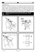
Page 7: ...1 25 2 3 4 1 2 25 mm 3 4 25 6 Date 01 2012 Revisione 18...

Page 8: ...ailable on our website http www far bo it Organization The tool must be used only by expert workers A protective visor and gloves must be put on when using the tool For topping up the oil we suggest u...

Page 9: ...d by some sealed gaskets which solve this problem MAIN COMPONENTS A Threaded tie rod B Head C Ring nut clamping head D Tensile strength pushbutton E Unscrewing pushbutton F Insertion Pin Hole Dechucki...

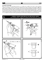
Page 10: ...turning the ring nut G to marked on the tool Place the insert on the tie rod and push slightly on it so as to make it clamp automatically Make sure the insert head touches the riveting tool head prop...

Page 11: ...order to dechuck the tie rod clutch at the same time unscrew the tie rod and extract it PICTURE 3 4 Keep the clutch dechucked and screw the tie rod size desired When the replacement of the tie rod ha...

Page 12: ...and while keeping the riveting tool in a horizontal position unscrew and close up the container X and the plug A WARNING it is very important to follow the about mentioned instructions and use gloves...

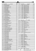
Page 13: ...36 711796 1 60C 710537 1 4 x 12 UNI 6873 37 711797 1 KIT D 741705 38 711798 1 20D 711705 2 39 711799 1 59D 711726 3 2 x 20 UNI 1707 40C 711800 1 C KIT E 741792 41 711801 1 32E 711792 1 42C 711802 1 C...

Page 14: ...connector 42C 711802 1 Clutch for tie rod 36 711796 1 Shaft 60C 710537 1 Spring pin 4 x 12 UNI 6873 37 711797 1 Milled sleeve KIT D 741705 Push button Kit 38 711798 1 Stroke adjusting nut 20D 711705...

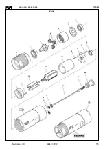
Page 15: ...29 33 6 32 E 31 30 99 E 63 E 85 62 26 62 22 61 61 73 79 64 80 17 18 70 74 78 16 A 56 59 D 81 71 19 86 55 5 23 1 72 A 83 20 D 98 10 7 16A x2 KIT D 77 84 4 59D x3 15 72A x2 9 20D x2 75 KIT A 88 87 89 9...

Page 16: ...SPARE PARTS F002 7 6 5 4 3 15 2 14 13 9 1 12 11 20 10 19 9 8 18 17 16 KIT A Revisione 18 Date 01 2012 15...

Page 17: ......

Page 18: ......

Page 19: ...www far bo it Organization FASTENING SYSTEMS HEAD OFFICE WAREHOUSE 40057 Quarto Inferiore Bologna Italy 20099 Sesto San Giovanni Via Giovanni XXIII 2 Milano Tel 39 051 6009511 Italy Ufficio Vendite F...

Reviews: