Fantech VHR 2004 Installation Manual Download Page 9

9

fantech

Exterior ducting installation

Weatherhood Location

•   Decide where your intake and exhaust hoods will be located.

Locating the Intake Weatherhood

•  Should be located upstream (if there are prevailing winds) from the 

exhaust outlet.

• At a minimum of 2m (6’) away from dryer vents and furnace exhaust 

(medium or high efficiency furnaces), driveways, oil fill pipes, gas meters, 
or garbage containers.

• At a minimum height of 460 mm (18’’) above the ground, or above the 

level of expected snow accumulation.

• At a minimum distance of 1m (3’) from the corner of the building.
• Do not locate in the garage, attic, crawl space, or underneath deck.

Locating the Exhaust Weatherhood

•  At least 460 mm (18") above ground or above the depth of expected snow accumulation
• At least 1m (3’) away from the corner of the building
• Not near a gas meter, electric meter or a walkway where fog or ice could create a hazard
• Do not locate in a garage, workshop or other unheated space

Installing the ducting to the weatherhoods

A well designed and installed ducting system will allow the HRV to operate at its maximum 
efficiency. The inner liner of the flexible insulated duct must be secured to the sleeve of the 
weatherhood (as close to the outside as possible) and to the appropriate duct connection on the 
HRV. The insulation should remain full and not crushed. The outer liner, which acts as a vapor 
barrier, must be completely sealed to the outer wall and the HRV using tape and/or caulking. A 
good bead of high quality caulking (preferably acoustical sealant) will seal the inner flexible duct to 
both the HRV duct connection and the weatherhood prior to securing them.
To minimize airflow restriction, the flexible insulated duct that connects the two outside 
weatherhoods to the HRV should be stretched tightly and be as short as possible.
Twisting or folding the duct will severely restrict airflow.

See “Installation Diagram Examples” for installation examples.

1

  Using the duct connection of 

the outside hood, outline the 
intake & exhaust holes to be 
cut. The holes should be slightly 
larger than the duct connection 
to allow for the thickness of the 
insulated flexible duct. Cut a 
hole for both the intake and 
exhaust hoods.

Push the hood into the opening 
and then attach the hood to the 
outside wall with mounting 
screws. 
Repeat the installation 
procedure for both the supply 
and exhaust hoods.

2

  Pull the insulated flexible duct 

through the opening until it is 
well extended and straight. 
Slide the duct’s inner vinyl sleeve 
over the hood duct connection 
and secure. Pull the insulation 
over the duct and pull the vapor 
barrier over the sleeve. Secure 
with appropriate tape or 
sealant.

4

  Using a caulking gun, seal 

around both hoods to prevent 
any leaks.

Steps for hood installation:

36" (1m)

min.

INTAKE

OUTSIDE CORNER

INSIDE CORNER

EXHAUST

18" (460mm) min.

18" (460mm) min.

6' (2m)

min.

36” (1m)

min.

Summary of Contents for VHR 2004

Page 1: ...ith the current edition of the National Building Code and or ASHRAE s Good Engineering Practices Fantech reserves the right to modify at any time and without notice any or all of its products features...

Page 2: ...vented combustion equipment i e Gas Furnaces Oil Furnaces Wood Stoves etc Products are designed and manufactured to provide reliable performance but they are not guaranteed to be 100 free of defects E...

Page 3: ...rhood 9 Steps for hood installation 9 INSTALLING DUCTS TO FROM INSIDE Installing ducting to HRV 10 Supply Exhaust Air Grilles Location 10 Ducting fifth port units R 10 DUCTING INSTALLATION EXAMPLES 11...

Page 4: ...loor area Bedrooms 0 1 2 3 4 5 6 7 7 Ft2 m2 CFM L s CFM L s CFM L s CFM L s CFM L s 1500 139 30 14 45 21 60 28 75 35 90 42 1501 3000 139 1 279 45 21 60 28 75 35 90 42 105 50 3001 4500 279 1 418 60 28...

Page 5: ...Due to the differences in pressure between the HRV and the equipment it is being connected to the HRV s airflow must be balanced on site using the procedure found in section AIRFLOW BALANCING Suggest...

Page 6: ...een the HRV and the equipment it is being connected to the HRV s airflow must be balanced on site using the procedure found in the section AIRFLOW BALANCING Fantech heat recovery ventilators HRV that...

Page 7: ...the equipment it is being connected to the HRV s airflow must be balanced on site using the procedure found in the section AIRFLOW BALANCING Fantech heat recovery ventilators HRV that use a supply fan...

Page 8: ...etrofitting Benefits Least expensive installation type Fantech heat recovery ventilators HRV that use a supply fan shutdown for frost preven tion do not include an outdoor air motorized damper If you...

Page 9: ...e outer liner which acts as a vapor barrier must be completely sealed to the outer wall and the HRV using tape and or caulking A good bead of high quality caulking preferably acoustical sealant will s...

Page 10: ...d from high wall or ceiling locations Grilles that diffuse the air comfortably are recommended In homes with a forced air furnace you may want to connect the HRV to the furnace ductwork see informatio...

Page 11: ...edicated system Simplified installation Option 1 Simplified installation Option 2 Bathroom Fresh Air Exhaust Air Central Control optional Fresh air to living room Exhaust CG 4 4 Adjustable Grill FEL 4...

Page 12: ...utside wall on which the supply and exhaust hoods will be mounted Have a nearby power supply 120 Volts 60Hz power cord is 3 feet long Mount the unit as level as possible in order to allow proper conde...

Page 13: ...10 is considered acceptable In the cases where the air flow is not exactly the same it is recommended to have a higher return air flow to ensure that the temperature of the supply air flow coming fro...

Page 14: ...also be made prior to any transition in the duct work so entire airflow is measured Measuring the airflow using station grid method Adjusting airflows A damper is integrated into the Fresh Air to Buil...

Page 15: ...40 minutes OFF and repeat EDF1 Press button a third time and the system will run continuously on HIGH speed EDF1R Press button a third time and the system will run recirculation on HIGH speed AUXILIAR...

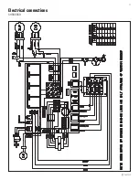
Page 16: ...16 fantech Electrical connections SHR1504 1505R 2004 2005R VHR1404 1505R 2004 2005R...

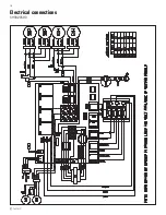
Page 17: ...17 fantech Electrical connections SHR3005R...

Page 18: ...18 fantech Electrical connections SHR3205RD...

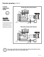
Page 19: ...t d ELECTRICAL CONNECTION TO FURNACE FOR A FURNACE CONNECTION TO A COOLING SYSTEM On some older thermostats energizing the R and G terminals at the furnace has the effect of energizing Y at the thermo...

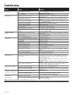
Page 20: ...uate power supply at site Have electrician check supply voltage Ductwork is restricting airflow Check duct installation Improper speed control setting Increase the speed of the HRV i e change unit con...

Page 21: ...uential damages incurred in the use of the ventilation system Fantech is not responsible for providing an authorized service centre near the purchaser or in the general area Fantech reserves the right...

Page 22: ...22 fantech Notes...

Page 23: ...tional du b timent du Canada ou aux m thodes d ing nierie appropri es de l ASHRAE Fantech se r serve le droit de modifier partiellement ou enti rement en tout moment et sans pr avis les caract ristiqu...

Page 24: ...ils de chauffage vacuation fournaise gaz fournaise mazout po le bois etc Les produits sont con us et fabriqu s pour fournir une performance fiable mais ils ne sont pas garantis 100 sans d faut M me le...

Page 25: ...otte 31 INSTALLATION DES CONDUITS INT RIEUR Installation des conduits sur le VRC 32 Emplacement des grilles d approvisionnement et d vacuation 32 Appareils munis d une cinqui me bouche R 32 EXEMPLES D...

Page 26: ...air recommand Superficie Chambre coucher 0 1 2 3 4 5 6 7 7 pi2 m2 Pi3 min L s Pi3 min L s Pi3 min L s Pi3 min L s Pi3 min L s 1500 139 30 14 45 21 60 28 75 35 90 42 1501 3000 139 1 279 45 21 60 28 75...

Page 27: ...ibrage du pr sent manuel d installation Installation sugg r pour Plinthe eau chaude Chauffage de planch Plinthe lectriques Thermopompe mural bibloc Avantages Fourni la meilleure r partition de l air f...

Page 28: ...distribu l int rieur Les ventilateurs r cup rateurs de chaleur VRC de Fantech qui utilisent un arr t du ventilateur d alimentation pour la pr vention de gel ne comprennent pas un volet motoris pour l...

Page 29: ...taill e dans la section quilibrage du d bit d air Les ventilateurs r cup rateurs de chaleur VRC de Fantech qui utilisent un arr t du ventilateur d alimentation pour la pr vention de gel ne comprennent...

Page 30: ...lisent un arr t du ventilateur d alimentation pour la pr vention de gel ne comprennent pas un volet motoris pour l air ext rieur Si vous utilisez une installation simplifi e c est dire relier de condu...

Page 31: ...l tement scell sur le mur ext rieur et le VRC l aide de ruban ou de produit de calfeutrage D posez un cordon de produit de calfeutrage de premi re qualit du mastic d isolation acoustique de pr f rence...

Page 32: ...oucher L air devrait provenir de la partie sup rieure d un mur ou du plafond Il est recommand d utiliser des grilles qui distribuent l air confortablement Dans les maisons pourvues d une fournaise air...

Page 33: ...s Air vacu Commande centrale en option Air frais achemin au salon Grille d vacuation CG4 Grille ajustable 4 po FEL 4 Coude 4 po 460 mm 3m HRV Chambres 460 mm Salle de bains Air frais Air vacu Commande...

Page 34: ...a ner l accumulation de charpie de poussi re ou de graisse dans le VRC et l endommager Montage Le raccordement de n importe quel type d appareils lectrom nagers au VRC annule la garanti 1 Installez le...

Page 35: ...entrant dans le syst me et s assurer que ces deux sont gaux Une diff rence de 10 ou moins est acceptable Dans ces les cas o il y a une d viation on recommande d avoir une plus grande quantit d air d c...

Page 36: ...es conduits afin de mesurer le d bit entier de l air Mesure du flot d air en utilisant la m thode du poste de mesure des d bits Ajustement des d bits d air Un registre est int gr dans le collet d air...

Page 37: ...utes ON 40 minutes OFF et r p ter EDF1 Appuyez le bouton une troisi me fois et le syst me fonctionnera en haute vitesse continuellement EDF1R Appuyez le bouton une troisi me fois et le syst me fonctio...

Page 38: ...38 fantech Sch mas lectrique SHR1504 1505R 2004 2005R VHR1404 1505R 2004 2005R NOTE ITEMS DESSIN S OR ENCERCL S EN LIGNES POINTILL E SONT SEULEMENT DISPOINIBLE POUR CERTAINS MOD LES...

Page 39: ...39 fantech Sch mas lectrique SHR3005R NOTE ITEMS DESSIN S OR ENCERCL S EN LIGNES POINTILL E SONT SEULEMENT DISPOINIBLE POUR CERTAINS MOD LES...

Page 40: ...40 fantech Sch mas lectrique SHR3205RD NOTE ITEMS DESSIN S OR ENCERCL S EN LIGNES POINTILL E SONT SEULEMENT DISPOINIBLE POUR CERTAINS MOD LES...

Page 41: ...ue l excitation de la borne Y du thermostat et cons quemment la mise sous tension du syst me de refroidissement Si votre syst me est muni d un tel type de thermostat vous devez respecter le c blage de...

Page 42: ...fficacit du VRC V rifiez le r seau de conduits Mauvais r glage de la commande de vitesse Augmentez la vitesse du VRC i e changez la vitesse de l appareil de vitesse R DUITE vitesse NORMALE avec le con...

Page 43: ...nu de respecter tous les codes en vigueur dans sa r gion Les pi ces y compris les pi ces de rechange pos es ult rieurement sont garanties pendant 5 ans partie de la date d achat de l appareil Les mote...

Page 44: ...to make technical changes For updated documentation please refer to www fantech net Fantech Fantech se r serve le droit de faire des changements tech niques Pour de la documentation jour s il vous pl...

Reviews: