background image

Figure 1

Dip Switch

ON    DIP

1     2    3     4      5

Receiver Unit

How to Wire Your Ceiling Fan

MAIN FUSE BOX

Figure 2

Figure 4

Green Wire

from Supply

(Ground)

White Wire

from Supply

White Wire

from Receiver 

Green Wire

from Hanger

Bracket (Ground)

Green Wire

from Hanger

Ball (Ground)

Listed

Outlet Box

Household

Supply

Black Wire

from Supply

Black Wire

from Receiver 

Receiver

Figure 3

x  6

WIRE

CONNECTORS

HARDWARE  USED:

Blue to Light

Black to Motor

White to Motor

all

To avoid possible electrical shock, be sure electricity

is turned off at the main fuse box before wiring

(Figure 2).

WARNING

NOTE:

If  you  are  not  sure  if  the  outlet  box  is

grounded, contact a licensed electrician for advice, as

it must be grounded for safe operation.

NOTE: If you feel that you do not have enough electrical 

wiring knowledge or experience, have your fan installed 

by a licensed electrician. 

Check to see that all connections are tight, including

ground, and that no bare wire is visible at the wire

connectors except for the ground wire. Do not

operate fan until the blades are in place. Noise and

motor damage could result.

WARNING

3.

After connections have been made, turn leads 

upward and carefully push leads into the outlet 

box, with the white and green leads to one side 

of the box and the black leads to the other side. 

(Figure 4) 

CAUTION:

INCORRECT WIRE CONNECTION WILL

DAMAGE THIS RECEIVER.

2.

 Connect green wires from hanger bracket and 

downrod to bare (ground) wire using wire connector. 

Connect black wire from receiver unit marked “AC IN L” 

to black supply wire using wire connector. Connect white 

wire from receiver unit marked “AC IN N” to white supply 

wire using wire connector. Connect white wire from 

receiver unit marked “TO MOTOR N” to white wire from 

fan using wire connector supplied with receiver unit. 

Connect black wire from receiver unit marked “TO 

MOTOR L” to black wire from fan using wire connector 

supplied with receiver unit. Lastly, connect blue wire 

from receiver unit to the blue fan light wire using wire 

connector supplied with receiver unit. (Figure 3) 

1.

To set the code on receiver unit, slide dip switches to

the same positions as set on the remote. (Figure 1)

NOTE: The remote unit has 32 different code 

combinations. To prevent possible interference from or to 

other remote units, simply change the combination code 

in the remote and receiver. 

NOTE:

Factory setting is all up. Do not use this position. 

11

Summary of Contents for SHOWROOM CELANO FP8062B Series

Page 1: ...E THESE INSTRUCTIONS Serial Number Purchase Date Español p MODEL FP8062B Questions problems missing parts Before returning to your retailer call our customer service department at 1 888 567 2055 8 a m 5 p m EST Monday Friday Net Weight 17 86 lbs 8 10 kgs CELANO v2 CEILING FAN 20 ...

Page 2: ...ades while the fan is operating 5 Do not operate reversing switch until fan blades have come to a complete stop Additional Safety Instructions 1 To avoid possible shock be sure electricity is turned off at the fuse box before wiring and do not operate fan without blades 2 All wiring and installation procedures must satisfy National Electrical Codes ANSI NFPA 70 and Local Codes The ceiling fan must...

Page 3: ... Hang Your Ceiling Fan How to Wire Your Ceiling Fan Installing Your Canopy Housing 8 10 11 12 7 How to Assemble Your Ceiling Fan Blades How to Operate Your Remote Control 14 How to Install Your Remote Control 15 How to Assemble Your Light Kit 13 Maintenance 15 How to Clean Your Ceiling Fan Blades 15 Parts List Exploded View Illustration Trouble Shooting 18 16 17 ...

Page 4: ...l or use fan if any part is damaged or missing This product is designed to use only those parts supplied with this product and or any accessories designated specifically for use with this product by Fanimation Substitution of parts or accessories not designated for use with this product by Fanimation could result in personal injury or property damage Contact your retail store for missing or damage...

Page 5: ... 15 Amp Circuit Electrical code requires use of a fan rated outlet box to support the extra weight and motion associated with a ceiling fan A fan rated box will be labeled as such and typically supports up to a 70lb ceiling fan Fan Rated Outlet Boxes vary in ratings and design Ensure the ratings of your ceiling fan outlet box meet the requirements for the ceiling fan being installed Figure 1 Figur...

Page 6: ...ween two joists and takes the place of wooden blocking To avoid fire or shock follow all wiring instructions carefully Any electrical work not described in these instructions should be done or approved by a licensed electrician WARNING Figure 3 CEILING JOIST CEILING OUTLET BOX To reduce the risk of fire electric shock or personal injury mount to outlet box marked acceptable for fan support of 15 9...

Page 7: ...Figure 3 1 Remove the two preassembled screws of the downrod support from the motor assembly then retain the screws for How to Assemble Your Ceiling Fan Step 4 Figure 1 2 Remove the six preassembled screws of the motor coupler washer from the motor assembly then retain the screws for Step 6 Figure 2 Motor Coupler Washer Motor Coupler Washer Downrod Support 4 Slide the blade through the slot in the...

Page 8: ...How to Assemble Your Ceiling Fan Downrod Set Screw Pin Hanger Ball 1 Remove the hanger ball portion from the downrod hanger ball assembly by loosening the set screw in the hanger ball until the ball falls freely down the downrod Remove the pin from the downrod then remove the hanger ball Retain the pin and hanger ball for reinstal lation in Step 6 Figure 1 2 Remove the hairpin clip and clevis pin ...

Page 9: ...wnrod Figure 3 Figure 4 Downrod Set Screws and Locking Nuts 2 Hairpin Clip Clevis Pin Figure 3 Figure 7 Motor Coupling Cover Ceiling Canopy Canopy Screw Cover 7 Cut off excess lead wire approximately 6 to 9 inches above top of the top of the downrod Strip insulationoff 1 2 inch from the end of each lead wire Figure 7 NOTE All set screws must be checked and retightened where necessary before instal...

Page 10: ...screw Figure 4 Cut off excess safety cable r r r fl r r of 4 WARNING The fan must be hung with at least 7 of clearance from floor to blades Figure 2 WARNING The outlet box must be securely anchored and capable of withstanding a load of at least 35 lbs Hanger bracket must seat rmly against outlet box If the outlet box is recessed remove wallboard until bracket contacts box If bracket and or outlet b...

Page 11: ...ING 3 After connections have been made turn leads upward and carefully push leads into the outlet box with the white and green leads to one side of the box and the black leads to the other side Figure 4 CAUTION INCORRECT WIRE CONNECTION WILL DAMAGE THIS RECEIVER 2 Connect green wires from hanger bracket and downrod to bare ground wire using wire connector Connect black wire from receiver unit mark...

Page 12: ...he neccessary wiring is completed Figure 2 Ceiling Canopy Canopy Screw Cover 1 Remove one of the two shoulder screws in the hanger bracket Loosen the second shoulder screw without fully removing it Assemble canopy by rotating key slot in canopy over shoulder screw in hanger bracket Tighten shoulder screw Fully assemble and tighten second shoulder screw that was previously removed Figure 1 WARNING ...

Page 13: ...embly and retain the screw for later Slightly loosen the remaining two screws Connect the 2 single pin connectors from motor assembly Figure 2 pin connectors from the LED assembly to the 2 single Light Plate Assembly Motor Assembly LED Assembly Figure 2 How to Assemble Your Light Kit Light Plate Assembly Figure 1 1 Remove one of the three screws in the support bracket at the bottom of the motor as...

Page 14: ...ke fan operational install 23A 12V battery included in hand held remote transmitter with fan power off Then follow the remote code setting process If not used for long periods of time remove battery toprevent damage to transmitter Store the remote away from excessive heat or humidly Figure 3 4 To set the remote code with a small screwdriver or ball point pen neither included slide dip switches fir...

Page 15: ... or harsh rags which can warp and ruin the finish 1 Periodic cleaning of your new ceiling fan is the only maintenance that is needed When cleaning use only a soft brush or lint free cloth to avoids cratching the finish Abrasive cleaning agents are not required and should be avoided to prevent damage to finish Reverse Switch Information Season Rotation Direction Switch Position Summer Counter Clock...

Page 16: ...anopy Screw Cover Assembly APGAC110RBL ADRAC1 45 PPAC1010 APPAC1101 AP1115 AMA8062B 7 10 Light Plate Assembly AP806203 11 Hand Held Remote RCCA04004000 12 Receiver Unit HDWFP8062B TR500 8 Blade Set Light Kit Glass Assembly 9 AP806206B AZ0871NI Fiber Washers 16 Wire Connector 4 Blade Mounting Hardware Bag Containing 3 16 24 Screws 16 Hardware Bag Containing Motor Coupling Cover Motor Assembly Hange...

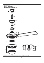
Page 17: ...2 3 4 5 6 10 11 7 12 8 9 Model FP8062B Exploded View Illustration Celano v2 NOTE The illustration shown is not to scale or its actual con guration may vary Product parts are subject to change without notice ...

Page 18: ...Check to make sure the screws which attach the fan blade to the motor assembly are tight 3 Check to make sure the screws which attach the fan blade to the motor assembly are tight CAUTION Make sure main power is turned off 4 Tighten set screw securely 1 Blades not attached to fan 2 Loose screws in motor housing 3 Screws securing fan blade to motor assembly are loose 3 Screws securing fan blade to ...

Page 19: ...Copyright 2019 Fanimation 2019 01 V 01 10983 Bennett Parkway Zionsville IN 46077 Phone 888 567 2055 Outside U S 317 733 4113 FANIMATION COM FAX 866 482 5215 ...

Page 20: ...ARDE ESTAS INSTRUCCIONES MODELO FP8062B VENTILADOR DE TECHO CELANO v2 Peso neto 8 10 kgs 17 86 lbs Fecha de compra Preguntas problemas piezas faltantes Antes de volver a la tienda llame a nuestro Departamento de Servicio al Cliente al 1 888 567 2055 8 a m 5 pm hora del Este de lunes viernes ...

Page 21: ... tierra a fin de prevenir posibles descargas eléctricas La instalación eléctrica debe ser llevada a cabo o aprobada por un electricista autorizado Se debe fijar bien la base del ventilador ésta debe ser capaz de soportar sin problemas al menos 15 9 kg 35 lb Consulte la página 3 25 del manual del propietario para ver los requisitos de soporte Si tiene dudas consulte a un electricista calificado Las...

Page 22: ...cilante y esto no debe considerarse un problema o defecto GARANTÍA LIMITADA DE POR VIDA Se extiende al comprador original de un ventilador Fanimation 7 Fanimation se reserva el derecho de modificar o discontinuar un producto en cualquier momento o sustituir cualquier pieza según lo establecido por esta garantía 8 En ningún caso se podrá devolver un ventilador sin previa autorización por parte de F...

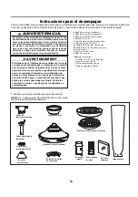
Page 23: ...uatro conectores de cables Cable de seguridad y Bolsa Tornillos 3 16 24 y arandela fibra aspas a buje del motor Unidad del motor del ventilador Unidad del soporte de suspensión Unidad del barral de la semiesfera Capuchón de techo Cubierta para el tornillo del capuchón Cubierta de unión del motor Ensamble de la placa de iluminación Ensamble del kit de iluminación el vidrio Juego de aspas Control re...

Page 24: ...s para asegurar un rendimiento eficiente del producto Apague el ventilador cuando no se encuentre en la habitación Los ventiladores son para refrescar a la gente no a las habitaciones Si la habitación está vacía apague el ventilador de techo para ahorrar energía Uso del ventilador de techo todo el año En verano Use el ventilador de techo en sentido contrario a las agujas del reloj El flujo de aire...

Page 25: ...de evitar incendios o descargas eléctricas siga con cuidado todas las instrucciones de instalación eléctrica Cualquier trabajo eléctrico que no se describa en estas instrucciones deberá ser realizado o aprobado por un electricista autorizado ADVERTENCIA No utilice este ventilador con un controlador variable de pared Rheostat o un regulador de intensidad Si lo hiciera podría dañar la unidad del man...

Page 26: ...tado sobre el volante del ensamble del motor Apriete los tornillos con cabeza de arandela junto con las arandelas de fibra para asegurar el aspa al volante del ensamble del motor Figura 4 Cómo ensamblar las aspas del ventilador de techo 2 Retire los seis tornillos preensamblados de la arandela del acoplador del motor del ensamble del motor y guárdelos para volverlos a instalar en el paso 6 Figura ...

Page 27: ...ador de techo 2 Retire el clip de horquilla y pasador de horquilla de la parte inferior de la bola para colgar Retener el pasador y clip para la reinstalación en el paso 4 Figura 2 1 Extraiga la pieza de la bola colgante de la unidad de la bola colgante varilla aflojando el tornillo de presión de la bola colgante hasta que la bola se libere de la varilla Retire el pasador del barral y luego extrai...

Page 28: ... Pele 1 2 cm del aislamiento en cada extremo del cable Figura 7 NOTA Se deben revisar todos los tornillos de fijación y volver a ajustarlos cuando sea necesario antes de realizar la instalación 1 5 2 4 c m a 2 2 8 6 c m 3 Lntroduzca los cables de color negro blanco y azu cables y cable de seguridad a través de la varilla Figura 3 Negro Blanco y Azul Cables y cable de seguridad 6 Vuelva a colocar l...

Page 29: ...rte de suspensión y la caja de conexiones de modo que más tarde se pueda realizar la instalación eléctrica AVERTISSEMENT La boîte de sortie doit être solidement ancrée et acceptable pour supporter un ventilateur de 15 9 kg 35 livres au moins Le support de suspension doit reposer fermement contre la boîte de sortie Si la boîte de sortie est encastrée retirez le panneau de revêtement jusqu à ce que ...

Page 30: ...ilador y coloque el ensamble de la bola para colgar varilla en la abrazadera para colgar que acaba de fijar a la caja de salida Asegúrese de que la ranura de la bola esté alineada con la lengüeta de la abrazadera para colgar Figura 4 5 Fije el cable de seguridad al cable de soporte para techo Deslice la abrazadera de cables por el cable de seguridad del ventilador Pase el extremo del cable a travé...

Page 31: ...l conductor azul de la unidad receptora al conductor azul de la iluminación del ventilador con el conector de cables que se adjunta con la unidad receptora Figura 3 Interruptores Unidad del receptor PRINCIPAL CAJA DE FUSIBLES Figura 3 x 6 Aditamentos utilizados Conectores de cable Conductor verde puesta a tierra desde la bola para colgar Azul Azul al motor Negro al motor Blanco al motor Negro Negr...

Page 32: ...de de la abrazadera para colgar Afloje el segundo tornillo de reborde sin retirarlo del todo Ensamble la base girando el chavetero de la base sobre el tornillo de reborde de la abrazadera para colgar Ajuste el tornillo de reborde Ensamble por completo el segundo tornillo de reborde que antes había retirado y ajústelo Figura 1 Para evitar posibles incendios o descargas eléctricas asegúrese de que l...

Page 33: ...r el tercer tornillo y asegure apriete Figura 1 2 Extraiga uno de los tres tornillos del ensamblede la placa de iluminación y guarde los tornillos para pasos posteriores Afloje levemente los otros dos tornillos Instale el conector 2 de pasadores desde unidad de luz LED conexión a la unidad del motor Figura 2 33 Figura 3 Figura 4 Vidrio Unidad de luz LED 4 Asegure el vidrio en al unidad de luz LED ...

Page 34: ...iempo extraiga la batería para evitar cualquier daño alejado del calor o la humedad excesiva Figrua 3 Figura 2 Figura 1 Solo para referencia visual no ha sido diseñado para cubrir todos los tipos de controles PRINCIPAL CAJA DE FUSIBLES 4 Para configurar el código del mando a distancia Mueva los interruptores de código hasta colocar el código de selección en la posición arriba o abajo Con un destor...

Page 35: ...el ventilador y aumenta la velocidad Figura 1 35 Cómo instalar su mando a distancia 1 Instalación de la placa de la pared Figura 1 Fije la placa de la pared usando los dos tornillos suministrados Figura 6 Interruptor del Reversa 6 Si desea que el flujo de aire se desplace en la dirección opuesta apague el ventilador y espere a que las aspas se detengan Luego deslice el conmutador inversor a la pos...

Page 36: ...ecomienda limpiar el polvo de las aspas periódicamente Lo mejor es utilizar un plumero Mantenimiento El único mantenimiento necesario para el ventilador de techo es una limpieza periódica Al llevar a cabo la limpieza use sólo un cepillo suave o un paño sin pelusas para evitar rayar el acabado No se requieren agentes abrasivos de limpieza los mismos deben evitarse para prevenir daños en el acabado ...

Page 37: ...odelo N FP8062B 1 2 3 4 5 6 Cubierta para el tornillo del capuchón APGAC110RBL ADRAC1 45 PPAC1010 APPAC1101 AP1115 AMA8062B 7 10 Ensamble de la placa de iluminación Ensamble del kit de iluminación el vidrio AP806203 11 Control remoto de mano RCCA04004000 12 Unidad del receptor HDWFP8062B TR500 8 9 Juego de aspas AP806206B AZ0871NI Cubierta de unión del motor Unidad del motor del ventilador Unidad ...

Page 38: ...10 38 1 2 3 4 5 6 7 8 9 Model FP8062B Ilustración del despiece Celano v2 NOTA la ilustración que se muestra no está hecha a es cala y su configuración real puede variar 11 12 ...

Page 39: ...s al ventilador 2 Hay tornillos flojos en la caja del motor 3 Los tornillos que aseguran los soportes de las aspas al buje del motor están flojos 1 Ajuste las aspas al ventilador antes de ponerlo en funcionamiento 2 Asegúrese de que todos los tornillos de la caja del motor estén bien ajustados pero no en exceso 3 Asegúrese de que los tornillos que fijan los soportes de aspas al buje del motor del ...

Page 40: ...019 Fanimation 2019 01 V 01 Visite nuestro sitio Web en www fanimation com 10983 Bennett Parkway Zionsville IN 46077 Llame sin cargo al 888 567 2055 FAX 866 482 5215 Desde fuera de los EE UU llame al 317 733 4113 ...

Reviews: