


Light Kit Assembly
Figure 3A
Figure 3B
FP6284**
FP6285B**
Switch Cup Assembly
Motor
Assembly
Motor
Assembly
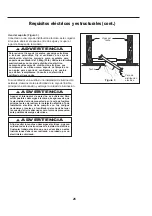
3A—FP6284**.
Securely attach the 9-pin connector from
the motor assembly to the wire harness socket within the
switch cup assembly. (Figure 3A)
3B—FP6285B**.
Securely attach the 9-pin connector from
the motor assembly to the wire harness socket within the
light kit assembly. (Figure 3B)
WARNING
The color label on these two connectors must
correspond to each other.
13
How to Assemble Your Switch Cup Assembly/Light Kit Assembly
(Continued)
Figure 4A
Figure 5
Figure 6
FP6284**
FP6285B**
Light Kit
Assembly
Light Kit
Assembly
Bulb
Glass
Nut
Finial
Trim Cover
Light Kit Assembly
Switch Cup
Assembly
4A—FP6284**.
Assemble the switch cup assembly to
the switch housing adapter using the previously removed
screws and securely tighten all screws. (Figure 4A)
4B—FP6285B**.
Assemble the light kit assembly to the
switch housing adapter using the previously removed
screws and securely tighten all screws. (Figure 4B)
NOTE:
If you have installed your fan without light kit (FP6284**)
skip Steps 5 and 6.
6.
Disassemble the finial, trim cover and nut in light kit
assembly. Securely attach the glass to light kit assembly
using supplied nut, trim cover and finial. Do not over
tighten. (Figure 6)
Figure 4B
5.
Insert light bulbs into sockets. (Figure 5)
NOTE:
When relamping is required, USE ONLY
MAX 9W, TYPE E26 DIMMABLE LISTED LED
(LIGHT) BULB.
RISK OF FIRE. USE ONLY LED LAMPS IN THIS
LIGHT KIT. INCANDESCENT AND HALOGEN LAMPS
MAY CAUSE SEVERE THERMAL DAMAGE.
CAUTION


