background image

20

3. GUARANTEE

Contact your distributor to find out its guarantee terms.

All FANELITE appliances are guaranteed against manufacturing and parts defects insofar as they are work

-

ing under normal operating conditions. Our appliances must be installed by qualified professionals in accor

-

dance with the regulations in force and the instructions given in these operating and assembly instructions. 

FANELITE reserves the right to apply or not the guarantee in case of negligence of the customer, defective 

installations, poorly adapted or not in conformity with the regulations in force.

Any damage related to any of the following points can not be taken into consideration and covered 

by our guarantee :

- Defects of supervision, maintenance and maintenance.

- Maintenance due to normal wear and tear.

- Maintenance of the product not in accordance with the instructions of the manual.

- Any adaptation of the product that would be necessary for compliance with the technical or safety standards 

applicable in a country other than that for which the product was originally designed and manufactured.

- Use or installation that does not conform to the use for which the product is intended or to the technical or 

safety standards in force in the country where it is used.

- Non-observance of instructions, safety precautions and instructions stipulated in the manual.

- A case of force majeure, sinister (fire, flood, etc.), lightning, etc.

- A modification or repair of the product not carried out by a qualified professional.

- Use of parts and accessories not compatible with the product or defective.

- Immediate or delayed damages resulting from improper handling during transport, mishandling, falling, 

shock, contact with water, sand or any other substance, etc.

- Improper treatment of the product due to inappropriate environment (poor aeration, exposure to moisture or 

strong heat, vibration, non-adapted power supply, surge, etc.).

Whether with respect to the purchaser, installer or any other person, our company cannot under any 

circumstances be held liable for any physical or material damage of any kind whatsoever, which may 

be caused by our products or which would be the direct or indirect consequence of the use of our 

products.

4. NOTES

In most houses, the ceiling fan is placed in the center of the room, replacing a light. In this way, the ceiling fan 

provides evenly distributed airflow throughout the room. 

Since a ceiling fan typically requires no more power than a light, the existing electrical circuit should not be 

overloaded. But if the ceiling fan is equipped with lamps, make sure the electrical circuit is strong enough to 

support the load. If this is not the case, you will need to install a new circuit with a new circuit breaker on the 

main electrical panel or an auxiliary panel so that the ceiling fan has its own circuit without powering any other 

device. If there is no central light in the room, you will need to define a location where the ceiling fan will be 

Summary of Contents for FANDC52LN

Page 1: ...www fanelite com MODE D EMPLOI NOTICE DE MONTAGE D INSTALLATION ET D UTILISATION USER MANUAL INSTALLING AND OPERATING MANUAL POUR MODÈLE FANDC52LN FOR MODEL FRANÇAIS ENGLISH ...

Page 2: ...ement afin de pouvoir la consulter en cas de besoin 1 Votre nouvel appareil 2 Consignes de sécurité 3 Garantie 4 Notes 5 Hauteur sous les pales 6 Contrôle au déballage 7 Fixation du support plafond 9 Assemblage 10 Suspension 12 Connexions électriques 11 Installation du récepteur dans le support plafond 13 Installation de la coupelle supérieure 14 Installation des piles dans la télécommande 15 Util...

Page 3: ...des sous le courant d air de l appareil Ne laissez pas les enfants jouer avec les sachets en polyéthylène ou le film d em ballage risque d étouffement Conservez l appareil dans un endroit frais et sec hors de la portée des enfants per sonnes âgées et handicapés Pour des raisons de sécurité ne laissez jamais l appareil sans surveillance pendant qu il fonctionne La distance minimale de sécurité entr...

Page 4: ...tion similaire afin d éviter un dan ger Ne déplacez ou débranchez jamais l appareil en tirant sur son câble d alimentation Éteignez et débranchez l appareil avant de le déplacer Transportez le dans son em ballage d origine Inspectez régulièrement et rigoureusement l appareil et ne l utilisez pas s il est en dommagé ou si vous voyez une quelconque détérioration ou dysfonctionnement Ne l utilisez pa...

Page 5: ...mélangez pas des piles usées avec des piles neuves ou différents types de piles Remplacez les piles uniquement par des piles neuves de même type Vérifiez que le couvercle du compartiment des piles est correctement fermé Danger d explosion si les piles ne sont pas remplacées correctement N utilisez jamais de piles présentant des fuites d électrolyte ou des fissures N ava lez pas la pile Si la pile ...

Page 6: ...on etc foudre etc Une modification ou réparation du produit non effectuée par un professionnel qualifié Utilisation de pièces et accessoires non compatible avec le produit ou défectueux Détériorations immédiates ou différées consécutives à une mauvaise manutention au cours du transport à une fausse manœuvre chute choc à un contact avec de l eau sable ou tout autre substance etc Un mauvais traiteme...

Page 7: ...a distance minimale recommandée entre le sol et les pales est de 230 cm Vous pouvez utiliser un mètre pour vérifier cette hauteur niveau de votre plancher limite inférieure des pales Si la distance entre le sol et les pales est inférieure au minimum recommandé ou si la structure de votre in térieur ne permet pas de respecter ce minimum vérifiez la longueur du tube de votre brasseur il est parfois ...

Page 8: ...ller le support plafond sur un plafond incliné de 15 maximum L ergot du support plafond doit dans ce cas être positionné au point le plus haut PLAFOND BOIS Positionnez le support à l endroit souhaitée et fixez le à l aide des vis fournies PLAFOND BÉTON Positionnez le support à l endroit souhaitée et marquez les trous à faire Retirez le support et percez la structure béton en faisant 2 trous corres...

Page 9: ...tirer la boule de suspension Etape 5 Retirer la coupelle supérieure Etape 6 Retirer la coupelle inférieure Etape 9 Retirer le tube de 18 cm Etape 10 Refaire à l inverse les étapes pour ré assemblage Si tube de 10 5 cm installer la cou pelle en 2 parties incluse avec le kit à la fin Si tube de 90 cm utiliser les exten sions de câbles incluses avec la rallonge de 90 cm Etape 2 Retirer la vis et bais...

Page 10: ... pales 10 SUSPENSION 1 INSTALLATION DU BRASSEUR DANS LE SUPPORT PLAFOND Prenez votre brasseur d air et placez la boule de suspension en haut du tube dans le support plafond Tournez le tube jusqu à ce que la boule de suspension se bloque dans le support plafond fente sur la boule de suspension dans l ergot du support Assurez vous que le brasseur d air soit bien bloqué A Fente sur la boule de suspen...

Page 11: ...RASSEUR AU RÉCEPTEUR Reliez le connecteur du brasseur MOTEUR 3 fils gris bleu noir à celui du récepteur Reliez le connecteur du brasseur LED 3 fils blanc jaune rouge à celui du récepteur Reliez le connecteur du brasseur COUPE CIRCUIT SÉCURITÉ 2 fils à celui du récepteur 2 CONNEXIONS DU RÉCEPTEUR AU SUPPORT PLAFOND Reliez le connecteur du support plafond 2 fils marron ou noir bleu à celui du récept...

Page 12: ...t sur le support plafond et tournez la jusqu à ce qu elle se bloque Faites attention de ne pas abîmer coincer les fils électriques 13 INSTALLATION DE LA COUPELLE SUPÉRIEURE Sens horaire Sens antihoraire LED MOTEUR SECURITE CABLE COUPE CIRCUIT SECURITE Vérifiez que les connexions ont bien été effectuées et que le récepteur et les fils sont correctement rangés dans le support ...

Page 13: ...arrière de la télécommande pour l en lever Insérez 2 piles 1 5V AAA en respectant la polarité Refermez le couvercle en le faisant glisser vers le haut 2 piles 1 5V AAA Arrière de la télécommande Couvercle des piles 15 UTILISATION DE LA TÉLÉCOMMANDE 1 DESCRIPTION Allumer Éteindre le brasseur Réduire la vitesse Augmenter la vitesse Régler la minuterie Pression simple Sélectionner le mode Pression lo...

Page 14: ...e choisie Aucun indicateur de mode ne s affiche sur l écran SLEEP L appareil diminue automatiquement sa vitesse d un niveau toutes les 30 minutes Sélec tionnez la vitesse de départ avant d activer le mode SLEEP L indicateur MODE SLEEP s affiche sur l écran lorsque ce mode est activé ECO L appareil fonctionne en mode éco à un niveau d efficacité énergétique élevé entre la vitesse 1 et 2 L indicateu...

Page 15: ... en cas de balancement anormal ou choc dans les pales Le cas échéant procédez à un contrôle de l appareil puis rallumez manuellement le brasseur d air à l aide de la télécommande 3 SYNCHRONISATION TÉLÉCOMMANDE RÉCEPTEUR Par défaut la télécommande et le récepteur sont déjà synchronisés ensemble Si la télécommande n est pas connectée au récepteur veuillez suivre les étapes ci dessous 1 Coupez l alim...

Page 16: ...nnec teurs Vérifiez que le courant arrive bien dans votre alimentation plafond Vérifiez qu aucun fil électrique ne soit endommagé Le brasseur oscille anormalement lorsqu il fonctionne Un brasseur vibre naturellement lorsqu il est en marche Même un brasseur bien équilibré cause de la vibra tion lorsqu il fonctionne 1 Vérifiez l état des vis des pales et resserrez les si nécessaire 2 Vérifiez que la...

Page 17: ... par les autres formes de réutilisation des appareils usagés Veuillez vous adresser à votre municipalité pour connaître la déchetterie compétente Indications relatives à la protection de l environnement 20 CONFORMITÉS La société LOGIFAN SARL et FANELITE EUROPE SAS déclare son produit FANDC52LN conforme aux directives suivantes en vigueur du Parlement Européen Directive concernant l harmonisation d...

Page 18: ...ce 18 Technical specifications 17 Troubleshooting 19 Environment protection ENGLISH 1 YOUR NEW APPLIANCE Dear Client Thank you for choosing this product This very innovative and very design product has been designed to provide you with maximum comfort and security Before using your appliance and for correct and safe use please read this manual carefully and strictly follow the safety instructions ...

Page 19: ...lm risk of choking Keep the appliance in a cool dry place out of the reach of children the elderly and the disabled For safety reasons never leave the appliance unattended while it is working The minimum distance between the floor and the blades must be at least 230 cm The ceiling fan hanger bracket must be fixed to the ceiling so as to support a mini mum weight of 68 kg The fixing must be made se...

Page 20: ... a hazard Never unplug or move the appliance by pulling on the power cable Turn off and unplug the appliance before moving it Carry the appliance in its original packaging Regularly and rigorously inspect the appliance and do not use it if it is damaged or if you see any deterioration or malfunction Do not use it if its blades or electrical wires are damaged if it dropped or if it has been damaged...

Page 21: ...not mix old batteries with new ones or different types of batteries Replace the bat teries only with new batteries of the same type Check that the batteries compartment cover is properly closed Danger of explosion if batteries are incorrectly replaced Never use batteries with electrolyte leaks or cracks Do not swallow the battery If the battery is swallowed seek medical advice immediately Never sh...

Page 22: ...re sinister fire flood etc lightning etc A modification or repair of the product not carried out by a qualified professional Use of parts and accessories not compatible with the product or defective Immediate or delayed damages resulting from improper handling during transport mishandling falling shock contact with water sand or any other substance etc Improper treatment of the product due to inap...

Page 23: ...eck this height level of your floor lower limit of the blades If the distance between the floor and the blades is less than the minimum recommended above or if the struc ture of your interior does not meet this minimum check the length of the tube of your ceiling fan it is some times possible to shorten it by few centimeters Do not forget however that a distance of 25 cm between the blades and the...

Page 24: ...maximum If your ceiling is inclined the lugs of the hanger bracket must be on the highest side of your ceiling Do not put it on the lowest side of your ceiling WOOD CEILING Position the support in the desired location and fix it using the screws provided CONCRETE CEILING Position the support in the desired location and mark the holes to be made Remove the support and drill the concrete structure b...

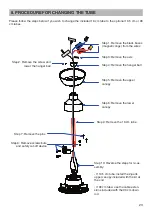
Page 25: ...Step 3 Remove the axis Step 4 Remove the hanger ball Step 5 Remove the upper canopy Step 6 Remove the lower canopy Step 9 Remove the 18 cm tube Step 10 Reverse the steps for re as sembly If 10 5 cm tube install the 2 parts upper canopy included with the kit at the end If 90 cm tube use the cable exten sions included with the 90 cm down rod Step 2 Remove the screw and lower the hanger ball Step 7 R...

Page 26: ...lades screws 10 HANG THE CEILING FAN 1 HANG THE CEILING FAN IN THE HANGER BRACKET Take your ceiling fan and put the hanger ball at the top of the tube into the hanger bracket Turn the tube until the hanger ball locks into the hanger bracket concave groove of hanger ball into the lugs of hanger bracket A Concave groove of hanger ball B Lugs of hanger bracket C Hanger bracket 2 INSTALL THE SECURITY ...

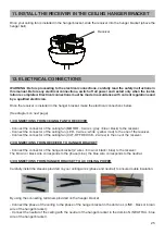
Page 27: ...grey blue black to the receiver Connect the connector of the ceiling fan LED 3 wires white yellow red to the one of the receiver Connect the connector of the ceiling fan CUT OFF DEVICE 2 wires to the one of the receiver 2 CONNECTIONS FROM RECEIVER TO HANGER BRACKET Connect the connector of the hanger bracket 2 wires brown or black blue to the receiver The brown or black wire corresponds to the pha...

Page 28: ...in place Be careful to not damage pinch the electrical wires 13 INSTALL THE CANOPY Turn clockwise Turn counter clockwise Receiver Hanger bracket Ceiling fan AC CEILING WIRES LED MOTOR CABLE ANTI FALL SAFETY CUT OFF DEVICE Check that all electrical connections have been correctly made and that the receiver and the wires are prop erly stored in the hanger bracket ...

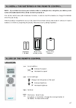
Page 29: ... cover on the back of the remote control downwards to remove it Insert 2 batteries 1 5V AAA by respecting the polarity Close the cover by sliding it upwards 2 batteries 1 5V AAA Back of the remote control Cover of the batteries 15 USE OF THE REMOTE CONTROL 1 DESCRIPTION Turn On Off fan Decrease the speed Increase the speed Set timer Short press Select mode Long press 3 seconds Change the running d...

Page 30: ...is dis played on the screen SLEEP The ceiling fan automatically decreases its speed by one level every 30 minutes Select the starting speed before activating SLEEP mode The MODE SLEEP indicator is displayed on the screen when this mode is activated ECO The ceiling fan operates in eco mode at a high energy efficiency level between speed 1 and 2 The ECO MODE indicator is displayed on the screen when...

Page 31: ... the motor in the event of abnormal balancing or shock in the blades If necessary check the ceiling fan then manually turn the ceiling fan on again using the remote control 3 PAIRING PROCEDURE REMOTE CONTROL RECEIVER By default the remote control and the receiver are already paired together If the remote control is not con nected to the receiver please follow the steps below 1 Turn off the power o...

Page 32: ...hat current is coming through your ceiling AC power supply Check that no electrical wires are damaged The ceiling fan oscillates abnormally during operation A ceiling fan vibrates naturally when it is working Even a well balanced ceiling fan causes vibration when it works 1 Check the condition of the screws of the blades and tighten them if necessary 2 Check that the hanger ball is securely locked...

Page 33: ...ate 97150 Saint Martin Antilles Françaises FANELITE EUROPE SAS 86 Avenue Gambetta 74000 Annecy France 20 CONFORMITIES The company LOGIFAN SARL and FANELITE EUROPE SAS declares its FANDC52LN product to comply with the following directives in force from the European Parliament Directive on the harmonization of the laws of the Member States relating to electromagnetic compatibility 2014 30 UE Directi...

Page 34: ...www fanelite com fanelitebrand ...

Reviews: