background image

17

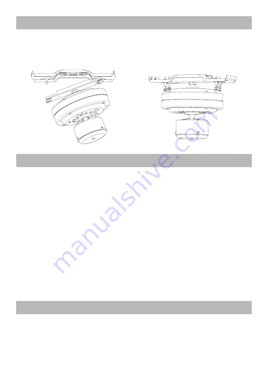
8. INSTALL THE MOTOR BLOCK

Take the motor block and position it correctly in its mounting bracket. Help you with the small safety hook on 

the mounting bracket.

Then tighten the 4 nuts and washers by using a suitable wrench. Make sure that you tighten the nuts properly 

to prevent a fall.

Make the following electrical connections before installing the motor cover and blades :

1/ Connect all the ground wires together : the ground wire of the ceiling with the 2 ground wires of the motor 

block and the one of the mounting ceiling support (yellow / green).

2/ Connect the ceiling neutral wire with the motor neutral wire (blue).

3/ Connect the ceiling phase wire with the motor phase wire (black) ; See section INSTALL THE WALL CON-

TROL.

4/ If you do not have the optional LED light kit, for safety isolate the light phase wire (red) in a separate domi-

no. If you have the LED light kit, connect the light phase wire (red) to a separate phase of your ceiling in order 

to control the light by an independent switch. See section INSTALL THE LIGHT KIT (OPTIONAL).

CAUTION:  Make  sure  that  the  wires  are  not  in  contact  with  the  motor,  the  motor  turning  at  high 

speeds when the ceiling fan is in operation.

9. ELECTRICAL CONNECTIONS OF THE CEILING FAN

WARNING : Before proceeding to the electrical connections, carefully read the safety instructions in 

this manual. Before any electrical connections, switch off all power and restart only when the instal-

lation is completed. Electrical connections must be made in accordance with current regulations and 

by a qualified electrician.

10. INSTALL THE MOTOR COVER

Once the electrical connections have been made, install the motor cover.

Loosen 2 of the screws halfway and remove the other 2 from the mounting ceiling support. Position the motor 

cover on the support by inserting the 2 screws, loosened halfway, in the notches of the motor cover, turn the 

motor cover counterclockwise until the screws lock in the notches. Replace the 2 other screws then tighten 

the 4 screws.

Summary of Contents for CANOUAN

Page 1: ...www fanelite com MODE D EMPLOI NOTICE DE MONTAGE D INSTALLATION ET D UTILISATION USER MANUAL INSTALLING AND OPERATING MANUAL POUR MOD LE 52YFT 1021 CANOUAN FOR MODEL FRAN AIS ENGLISH...

Page 2: ...de s curit ci apr s Conservez cette notice pr cieusement afin de pouvoir la consulter en cas de besoin 1 Votre nouvel appareil 2 Consignes de s curit 3 Garantie 4 Notes 5 Hauteur sous les pales 6 Con...

Page 3: ...es Ne laissez jamais d enfants de personnes g es ou malades sous le courant d air de l appareil Ne laissez pas les enfants jouer avec les sachets en poly thyl ne ou le film d em ballage risque d touff...

Page 4: ...eil doit tre reli une mise la terre efficace Si le c ble d alimentation est endommag il doit tre remplac par le fabricant son service apr s vente ou des personnes de qualification similaire afin d vit...

Page 5: ...ns des conditions normales d utilisation Nos appareils doivent tre install s par des professionnels qualifi s conform ment la r glementation en vigueur et aux instructions figurant dans cette notice d...

Page 6: ...seur d air et d ajuster la r sistance de votre installation si n cessaire Le support plafond doit imp rativement tre soutenu par la structure du plafond Votre installation doit galement pouvoir r sist...

Page 7: ...moins 68 kg en tirant dessus Nous d clinons toute responsabilit en cas de chute du brasseur d air PLAFOND BOIS Positionnez le support l endroit souhait e et fixez le l aide des vis et rondelles fourn...

Page 8: ...e votre plafond afin de contr ler la lumi re par un interrupteur ind pendant Voir section INSTALLATION DU KIT LUMI RE OPTIONNEL ATTENTION Assurez vous que les fils lectriques ne sont pas en contact av...

Page 9: ...de s curit pr sentes dans cette notice Avant tout raccord lectrique coupez toute alimentation et remettez en service uniquement lorsque l installation sera enti rement termin e Les connexions lectriq...

Page 10: ...lez suivre les tapes ci dessous 1 Retirez le cache sous le brasseur en enlevant les 3 vis rondelles et la pi ce centrale 2 Retirez l crou et la rondelle du kit lumi re Passez les 3 fils et connecteurs...

Page 11: ...kit lumi re celui du fil bleu du brasseur d air retirez au pr alable le connecteur du fil bleu brasseur qui assure la double isolation s curit si utilisation du brasseur d air sans kit lumi re c Conn...

Page 12: ...2 cm 17 PROTECTION DE L ENVIRONNEMENT Au terme de sa dur e de vie ce produit ne doit pas tre limin avec les ordures m nag res mais doit tre remis un point de collecte destin au recyclage des appareils...

Page 13: ...ontrol 15 Cleaning and maintenance 16 Technical specifications 17 Environment protection ENGLISH 1 YOUR NEW APPLIANCE Dear Client Thank you for choosing this product This very innovative and very desi...

Page 14: ...ildren play with polythene bags or wrapping film risk of choking Keep the appliance in a cool dry place out of the reach of children the elderly and the disabled For safety reasons never leave the app...

Page 15: ...rounding system If the power cable is damaged it must be replaced by the manufacturer its af ter sales service or persons of similar qualification in order to avoid a hazard Never unplug or move the a...

Page 16: ...he instructions given in these operating and assembly instructions FANELITE reserves the right to apply or not the guarantee in case of negligence of the customer defective installations poorly adapte...

Page 17: ...n and adjust the resistance of your installation if necessary The ceiling fan mounting bracket must be supported by the ceiling structure Your installation must also be able to withstand the vibration...

Page 18: ...t We decline all re sponsibility in the event of a fall of the ceiling fan WOOD CEILING Position the support in the desired location and fix it using the screws and washers provided CONCRETE CEILING P...

Page 19: ...e wire red to a separate phase of your ceiling in order to control the light by an independent switch See section INSTALL THE LIGHT KIT OPTIONAL CAUTION Make sure that the wires are not in contact wit...

Page 20: ...read the safety instructions in this manual Before any electrical connections switch off all power and restart only when the instal lation is completed Electrical connections must be made in accordanc...

Page 21: ...off all power and restart only when the instal lation is completed Electrical connections must be made in accordance with current regulations and by a qualified electrician 12W LED light kit sold as...

Page 22: ...ctor of the blue wire of the light kit to the one of the blue wire of the ceiling fan first remove the connector of the blue fan wire which ensures double insulation safety if using the fan without li...

Page 23: ...atts Diameter 132 cm 17 ENVIRONMENT PROTECTION Do not dispose of this product in the usual household garbage at the end of its life cycle hand it over a collec tion point for the recycling of electric...

Page 24: ...www fanelite com fanelitebrand...

Reviews: