background image

- 4 -

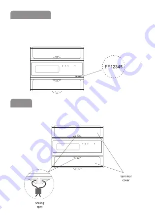
The meter is marked with individual serial number allowing its 

unambiguous identification. The marking is laser engraved and 

cannot be removed).

The meter has sealable input and output terminal covers to pre-

vent  any attempts to bypass the meter.

Meter number

Sealing

- 4 -

Summary of Contents for LE-03M CT

Page 1: ...e elec tricity system Serial RS 485 and implemented Modbus RTU communication protocol allows the indicator used in networks for remote re ading of data Purpose F F Filipowski sp j Konstantynowska 79 81 95 200 Pabianice POLAND phone fax 48 42 215 23 83 48 42 227 09 71 www fif com pl e mail biuro fif com pl Donotdisposeofthisdeviceinthetrashalongwithotherwaste According to the Law on Waste electro c...

Page 2: ...ts Ip of the transformers that can be used are stored in the memory of the meter The selection of appropriate value which corresponds to the values of the con nected transformers results in automatic setting of appropriate coefficient according to which the actual value of consumed electric energy of the system is calculated This value is indica ted on the LCD in a format that depends on the trans...

Page 3: ...current transformer 5 A When using a dedicated transformer the number of pulses per 1 kWh is calculated from the formula 12000 5 Ip where Ip primary current of the transformers used Example for 5 5A transformer Ip 5 12000 5 5 12000 pulses kWh for 100 5A transformer Ip 100 12000 5 100 600 pulses kWh Change of meter address is done via the RS 485 port using the Modbus RTU protocol command to set the...

Page 4: ...idual serial number allowing its unambiguous identification The marking is laser engraved and cannot be removed The meter has sealable input and output terminal covers to pre vent any attempts to bypass the meter Meter number Sealing 4 ...

Page 5: ... 5 Wiring diagram ...

Page 6: ... 6 1 6 voltage terminals 8 pulse output 9 pulse output 10 RS 485 output B 11 RS 485 output A 15 18 current terminals Description of terminals Dimensions ...

Page 7: ...sformer is opened during operation there is a risk of high voltage on the secondary winding In order to protect personnel opera ting the device it is recommended to ground one end of the secondary winding of each transformer Do not tighten the terminals without an inserted wire This may damage the clamping mechanism or the plastic cover of the terminal 6 Connect the RS 485 network cables to the te...

Page 8: ... 9600 bps Parity NONE Stop bits 1 Modbus address factory settings 1 245 Measurement registers address description com mand type atr 0 Active energy R0 03 int R 1 Active energy R1 03 int R 2 Active energy R2 03 int R 6 Meter address 06 int W Legend R read W write Modbus RTU protocol parameters ...

Page 9: ... R3 x where R0 register number 0 R1 register number 1 R2 register number 2 R3 register number 3 x factor depending on Ip current setting The value of x in the Ip current ranges 5 75 100 80 750 10 80 6000 1 To set the value of the Ip current number one must give a specific number for the Ip value e g value 8 for a 100 5 transformer see table of projection numbers and formats for Ip currents ...

Page 10: ... 99999 99 30 3 99999 99 40 4 99999 99 50 5 99999 99 60 6 99999 99 75 7 99999 9 80 8 99999 9 100 9 99999 9 120 10 99999 9 125 11 99999 9 150 12 99999 9 200 13 99999 9 250 12 99999 9 300 13 99999 9 400 14 99999 9 500 15 99999 9 Table of projection numbers and format for Ip currents ...

Page 11: ...at LCD projection 600 16 99999 9 750 17 99999 9 800 18 99999 1000 19 99999 1200 20 99999 1250 21 99999 1500 22 99999 2000 23 99999 2500 24 99999 3000 25 99999 4000 26 99999 5000 27 99999 6000 28 99999 Table of projection numbers and format cont ...

Page 12: ...r consumption 10 VA 2 W load capacity of current inputs 0 4 VA indication range depends on the gear constant depends on the gear signalling current consumption A B C phases 3 red LED read out signalling red LED communication port RS 485 communication protocol Modbus RTU transmission parameters 9600 bps parity NONE stop bits 1 pulse output type open collector maximum voltage 27 V DC maximum current...

Page 13: ...required F F products are covered by a 24 month warranty from the date of purchase The warranty is only valid with proof of purchase Contact your dealer or contact us directly F F Filipowski sp j declares that the device is in conformity with the essential requirements of The Low Voltage Directive LVD 2014 35 EU and the Electromagnetic Compatibility EMC Directive 2014 30 UE The CE Declaration of C...

Page 14: ...and overvoltage circuit breakers Before connecting the power supply make sure that all cables are connected correctly It is essential to observe the operating conditions of the meter supply voltage humidity temperature To avoid electric shock or damage to the meter turn off the power supply whenever the connection is changed Do not make any changes to the unit yourself Doing so can result in damag...

Page 15: ......

Reviews: