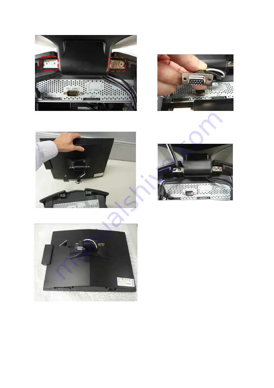
background image


12 


TOP I/O Ports and   

Main LCD Unit Securing Screws   

(as RED marks indicated) 


Detach the Main LCD Unit from the Base Unit. 


Main LCD Unit with MSR Module. 


4.  Disconnect the COMBO USB 

Connector from the   

TOP I/O Port. 


5.  Use a screw driver to remove the 

four securing screws of the   

Main LCD Unit. 


Note: 

Main LCD Unit is an integrated part and should not dissemble or modify.   

ANY ATTEMPT OF MODIFICATION OR DISSEMBLE IS PROHIBITED AND THE WARRANTY 

OF THIS PRODUCT IS TERMINATED IMMEDIATELY. 

Please contact the authorized and certificated technical personnel for maintenance. 

Summary of Contents for TP-8515

Page 1: ...1 Service Manual TP 8515 Modular POS System Service Manual TP 8515 Version 1 0 Copyright Fametech Inc TYSSO 2018 ...

Page 2: ...y Optional 17 C Remove the HDD SSD Drive from POS Unit 19 D Modular Main Board Set 21 a Remove the Modular Main Board Set from the POS Unit 21 b Remove the Power Adaptor from the Modular Main Board Set 23 c Remove the HDD SSD Drive from the Modular Main Board Set 24 d Disconnect the HDD Cable 26 e Disconnect the Parallel PRT Port for Customized Model ONLY 27 f Remove the Speaker Audio from Main Bo...

Page 3: ...ing Your POS Terminal Parts Descriptions Figure 1 Parts of POS Unit TOP I O Cover A Main LCD Display B Base Unit Side Cover Left Side Cover Right Modular Main Board Set C Modular Customer Display D 2 nd LCD Display A1 MSR A2 Button ...

Page 4: ...al Peripherals A1 MSR Optional MSR Reader on the side of Main LCD Display A2 i Button Optional i Button Module on the side of Main LCD Display C Modular Customer Display Optional Customer Display D 2nd LCD Display Optional Secondary 2nd LCD Display The optional peripherals and parts may not include in the product Please contact the local representatives or technical support personnel of the provid...

Page 5: ...connect the HDD cable to the Hard Drive Connector Slot Connection Installation Notes Memory Slot 1 Install the RAM module to the main board SATA Connectors Please use the SATA HDD cable and connect to the Hard drive USB Connect to the devices that support USB interface COMBO USB Connect to the optional MSR Module and the USB port under the Main LCD Display PWR LED PWR SW Connect to Power Switch an...

Page 6: ... COM 2 LPT1 Parallel Port COM 5 COM 6 SATA DATA Connectors Memory Slot 1 Main Slot VGA 1 COM 3 SATA POWER CN4 COMBO USB LAN USB 3 4 USB 1 USB 2 CASH 1 VGA_Power VJ1 PWR_IN Speaker SP1 COM Jumper 1 6 JLPC1 MINI CARD 1_1 COM 4 MIC1 LOUT1 JCMOS1 JCASE1 ...

Page 7: ...5 Front View Layout ...

Page 8: ...6 Rear View LVDS eDP ...

Page 9: ...7 Rear View Layout Figure 2 Main Board Note The eDP connector is for customized model Only and is not available for standard model ...

Page 10: ...eipt Printer Secondary LCD Display Disconnect all the devices or cables connected to the POS terminal Disconnect and remove the Power Adaptor from the POS terminal Unplug the power cables from the electrical outlet Note There are no serviceable parts or components in the POS system or peripherals DO NOT modify any parts of POS systems or use non qualified parts or peripherals Store the disconnecte...

Page 11: ...al outlet a Unplug the cables from the POS unit Place the POS terminal onto a stable and flat location Examine the bottom of Main LCD Display Main Power Switch of POS Unit on the bottom of Main LCD Display 1 Examine the bottom of Main LCD Display Disconnect the device of the USB port if connected USB port of Main LCD Display 2 Lift up the whole POS unit and examine the Bottom I O ports beneath the...

Page 12: ...ed 3 Disconnect the Power Cable from the POS unit Disconnect the Power Cable from the Power Adaptor 4 Disconnect all of the connected cables on the Bottom I O Ports Note Always store the Power Cable and the other disconnected cables devices in a secure location for further use ...

Page 13: ...nnector with HEX Head Screws 1 Press the two sides and pull up to remove the TOP I O Cover Top I O Cover 2 There are LVDS cable and COMBO USB cable in the Base Unit Unplug the LVDS cable Unplug the LVDS Cable 3 Use a HEX screw driver to remove the HEX screws of the COMBO USB Connector Remove the HEX Head Screws ...

Page 14: ...nnector from the TOP I O Port 5 Use a screw driver to remove the four securing screws of the Main LCD Unit Note Main LCD Unit is an integrated part and should not dissemble or modify ANY ATTEMPT OF MODIFICATION OR DISSEMBLE IS PROHIBITED AND THE WARRANTY OF THIS PRODUCT IS TERMINATED IMMEDIATELY Please contact the authorized and certificated technical personnel for maintenance ...

Page 15: ...MSR Module with Protective Caps and Securing Screws 1 Remove two Protective Caps of MSR Module with care 2 Use a screw driver to loosen and remove the securing screws Loosen the securing screws of MSR Module 3 Disconnect the ribbon cable connector of MSR Module from the Main LCD Unit Disconnect the MSR Module from the Main LCD Unit ...

Page 16: ...ctive Cover Left 4 Side I O Port Protection If the Side I O Port of the Main LCD Unit is not in use please install the protect cover onto the I O Port Note Always store the detached MSR Module or i Button and screws in a secure location for further use ...

Page 17: ...ess the two sides and pull up to remove the TOP I O Cover Top I O Cover 2 Lift up the POS Unit and examine the Bottom I O connectors Disconnect the connectors of Secondary LCD Display Disconnect the VGA Connector from the Bottom I O Ports 3 Use a screw driver to remove the four securing screws of the Secondary LCD Display ...

Page 18: ...ary LCD Display detached Secondary LCD Display 4 Arrange the cables and remove the Secondary LCD Display from the Base Note Store the detached Secondary LCD Display and securing screws in a secure location for further use ...

Page 19: ...the two sides and pull up to remove the TOP I O Cover Top I O Cover 6 Lift up the POS Unit and examine the Bottom I O connectors Disconnect the connectors of Customer Display Disconnect the Connectors of Customer Display from the Bottom I O Ports 7 Use a screw driver to remove the four securing screws of the Customer Display ...

Page 20: ...Display detached Customer Display 8 Arrange the cables and remove the Secondary LCD Display from the Base Unit Note Store the detached Customer Display and securing screws in a secure location for further use or maintenance ...

Page 21: ... face down on the surface Note To prevent injuries to the LCD Panel Carefully lay the front of the POS face down on a flat clean and stable surface with additional cushioned material for example blanket 2 Loosen the Securing Screws Of The HDD Drive Slot Loosen the Securing Screw of the HDD Drive Slot 3 Pull out the HDD Drive Module Pull out the HDD Drive Module ...

Page 22: ...ctly Incorrect installation of HDD module may cause the system not functioning When Re installing the HDD SSD Module Beware the Direction of HDD SSD module when re install it back to the POS Unit Make sure the securing screw hole is matches to the HDD Drive Slot of POS Unit DO NOT install the module in Wrong direction To re install the HDD SSD module back to the POS Unit DO NOT Push or pull the HD...

Page 23: ...e Base of the POS Unit Pull out the Main Board Set from the Base Loosen and remove the securing screws from the POS Unit as RED marks illustrated Remove the Securing Screws of the Modular Main Board Set Note Before remove the Main Board Set Make sure all of the connectors of the I O Ports Bottom and TOP are disconnected ...

Page 24: ...22 Modular Main Board Unit Power Adaptor Note Store the screws in a secure location for further use ...

Page 25: ...uring Screws of Power Adaptor Power Adaptor with Metal Brackets and Securing Screws Loosen and remove the securing screws of the Metal Brackets Then detach the Power Adaptor from the Main Board Set Remove the Securing Screws of the Metal Brackets Note Store the brackets screws and Power Adaptor in a secure location for further use ...

Page 26: ...rd Set Main Board Set HDD SSD Drive removed 1 Use a screw driver to remove the HDD SSD Drive from the Modular Main Board Set Please refer to C Remove the HDD SSD Drive from POS Unit Loosen the Securing Screw of HDD SSD Drive Slot 2 Remove the HDD Connector from the Metal HDD Slot Loosen the Securing Screws on the Metal HDD Slot ...

Page 27: ...lot Left and Modular Main Board Set Right 3 There are two securing screws on the Metal HDD Slot Use a screw driver to remove the Metal HDD Slot from POS Unit Loosen and Remove the Securing Screw of Metal HDD Slot A Loosen and Remove the Securing Screw of Metal HDD Slot B DATA Connector Power Connector ...

Page 28: ...e Main Board Disconnect the connectors of HDD Cable from the Main Board Note There is a cable binder on the HDD cable Cut the cable binder before disconnect the HDD cable Store the HDD cable in a secure location for further use Remember to use a new cable binder to arrange and re tighten the cables on the Main Board Set when the maintenance is completed ...

Page 29: ...allel Port PRT removed Detached Parallel Port 1 Disconnect the connector of Parallel Port from the Main Board The Connector of Parallel Port on the Main Board 2 Use a HEX screw driver to remove the securing screws of 25 pin Parallel Port connector Loosen the HEX Head Securing Screws of Parallel Port Connector ...

Page 30: ...f Speaker Audio Connector Speaker and Securing Screws Disconnect the Red Black twisted cable of Speaker from the Main Board 1 Disconnect the Speaker from Main Board Disconnect the Red Black twisted cable from the Main Board 2 Loosen the securing screws and remove the Speaker ...

Page 31: ...ed COM Port 1 Disconnect the connector of COM Port from the Main Board The Connector of COM Port COM 4 on the Main Board 2 Use a HEX screw driver to remove the securing screws of COM Port connector Loosen the HEX Head Securing Screws of COM Port Connector COM 4 ...

Page 32: ...he two sides of the RAM module slot 2 Gently slide the module out of the slot To Replace or Re Install the RAM Module Install the RAM Module to the RAM Module slot Press the Module until the two latches tighten the RAM Module and firmly installed Note Store the RAM Module in a secure location for further use ...

Page 33: ...DB9 COM Ports COM 1 2 3 and VGA Port Securing Screws of Main Board as Yellow Marks indicated 1 Bottom I O Ports Use a HEX screw driver to remove the securing screws of COM Port connectors and VGA Port 2 Main Board Securing Screws Remove the securing screws of the Main Board ...

Page 34: ... O Port Use a HEX screw driver to remove the securing screws of COMO USB Port 4 Remove the securing screws of Metal Bracket of TOP I O Port Securing Screw of TOP I O Bracket 5 Slide and remove the Main Board from the Metal Bracket of Main Board Set Note Remove all of the HEX Head Screws of connectors and store to a secure location for further use ...

Page 35: ...OSE OF USED BATTERIES ACCORDING TO THE INSTRUCTIONS REGULATIONS OF LOCAL AUTHORITY Before Replacement 1 Make sure the POS terminal is power off and the Power Cord is unplugged 2 The Main Board should be in a stable state and place to a stable location 3 Make Sure the Main Board is not connected to any other power source or device that may transmit electricity to the Main Board 4 Use only the same ...

Page 36: ...r parts replacement please purchase the service parts from manufacturer or authorized distributer ONLY The Base Unit with two Side Covers Press the edge and pull up the Side Cover Base Unit Bottom View Press the edge and pull up to remove the Side Covers Install the new Side Covers to the Base Unit ...

Page 37: ...35 Revision History Date Version Note Description Mar 05 2018 Ver 1 0 Preliminary version TP 8515 Disassemble Instruction ...

Reviews: