FALK FLUID COUPLINGS —
Refer to the installation manual
furnished with the fluid coupling for installation, alignment and
startup instructions.
GAP AND ANGULAR ALIGNMENT —
If possible, after
mounting coupling hubs, position the driving and driven equipment
so that the distance between shaft ends
is equal to the coupling gap. Align the
shafts by placing a spacer block, equal
in thickness to required gap, between
hub faces, as shown above, and also at
90
°
intervals around the hub. Check
with feelers.
OFFSET ALIGNMENT —
Align
driving and driven shafts so that a
straight edge will rest squarely on both
couplings hubs as shown to the right
and also at 90
°
intervals. Tighten
foundation bolts of the connected
equipment and recheck alignment
and gap.
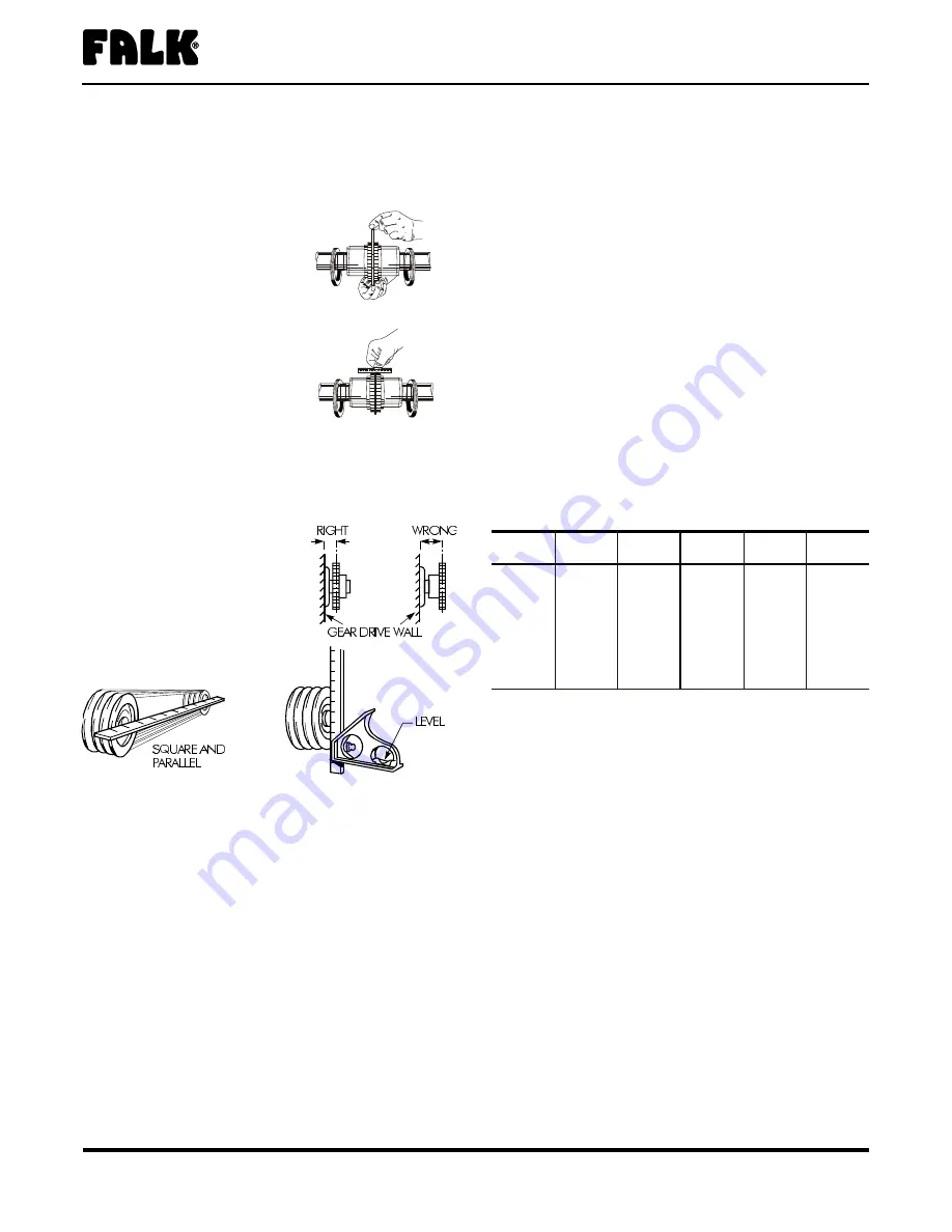
SPROCKETS, PULLEYS OR SHEAVES —
Mount power
take-offs as close to the gear drive housing as possible to
avoid undue bearing load and shaft deflection.
Align the output shaft of the gear drive square and parallel with
the driven shaft by placing a
straightedge across the face of the
sprockets or sheaves as illustrated.
Check horizontal shaft alignment
by placing one leg of a square
against the face of the sheave or
sprocket with the spirit level on
the horizontal leg of the square.
DO NOT over tighten belts or chains. Adjust chains to
manufacturers’ specifications. Adjust belts as follows:
The ideal tension is the lowest tension at which the belt will not
slip under peak load conditions. Check the belt tension
frequently during the first 24 to 48 hours of run-in operation.
Over tightening belts shortens belt and bearing life. Keep belts
free from foreign material which may cause slippage. Inspect
the V–belt periodically; tighten the belts if they are slipping.
OUTBOARD BEARING —
Mount the outboard bearing and
gear drive on a common foundation so that they will shift as an
assembly if settling should occur. Bring the outboard bearing to the
correct horizontal position with broad flat shims under the mounting
pad. Align accurately so that the load is equally divided between
the two drive bearings and the outboard bearing. Mount a stop bar
against the pillow block foot on the load side when large horizontal
load components are exerted on the pillow block.
PINION MOUNTING —
Mount pinion as close to the unit as
possible to avoid undue bearing load and shaft deflection. Refer
to the Factory for pinion alignment instructions.
BACKSTOPS —
To prevent damage to backstops due to
incorrect motor shaft rotation at start up, couplings are NOT
assembled when gear drives are furnished with backstops. After
completing the electrical connection, check motor and gear
drive shaft rotations. Then complete alignment and assembly
of coupling.
Fastener Tightening Torques
Use the tightening torque values specified in
for
fastening Falk gear drives, motors, keeper plates and accessories to
their mounting surfaces with non-lubricated fasteners. DO NOT use
these values for “torque locking” fasteners or for fastening
components with aluminum feet or with soft gaskets or vibration
dampers on the mounting surface. If the tightening torque exceeds
the capacity of the torque wrench, use a torque multiplier. Use
Grade 5
fasteners for diameters through 1.50", for larger
diameter
fasteners,
use
ASTM A-354 Grade BC.
Water Cooling
WATER COOLED HEAT EXCHANGERS
—
Install a shut-off or
control valve in the water line to the heat exchanger to regulate
the water flow through the exchanger. Also install a water flow
gauge between the control valve and the exchanger to
determine actual flow rate. Discharge water to an OPEN DRAIN
to prevent back pressure.
Lubrication Recommendations
Carefully follow lubrication instructions on the gear drive
nameplate, warning tags and installation manuals furnished with
the gear drive.
Lubricants listed in this manual are typical ONLY and should not
be construed as exclusive recommendations. Industrial type
petroleum based rust and oxidation inhibited (R & O) gear
lubricants or industrial type sulfur-phosphorus extreme pressure
(EP) gear lubricants are the recommended lubricants for
ambient temperatures of 15
°
F to 125
°
F(-9
°
C to +52
°
C).
For drives operating outside the above temperature range refer
to
“Synthetic Lubricants” paragraphs, Page 4.
lubricants can also be used in normal climates.
The Falk Corporation, a Sundstrand Company, P.O. Box 492, Zip 53201-0492
148-050
3001 W. Canal St., Zip 53208-4200, Milwaukee, WI USA Telephone : 414-342-3131 April 1999
Fax: 414-937-4359 e-mail: [email protected] web: www.falkcorp.com
Supersedes 4-89
Enclosed Gear Drives
•
Installation & Maintenance Instructions
Types GHB, Y, YB & YBX
•
Sizes 1080–1195 & 2050–2235 (Page 3 of 8)
TABLE 1 —
Tightening Torques – lb-in
DO NOT LUBRICATE FASTENERS
Thread
Dia-UNC
Metal
to Metal
Metal to
Concrete
Thread
Dia-UNC
Metal
to Metal
Metal to
Concrete
.250-20
90 70
1.250-7
12600 10000
.3125-18
185 145
1.375-6
16500 13000
.375-16
330 255
1.500-6
22100 17500
.500-13
825 640
1.750-5
23700 18700
.625-11
1640 1280
2.000-4.5
37000 29000
.750-10
2940 2290
2.250-4.5
52000 41000
.875-9
4560 3750
2.500-4
72000 56000
1.000-8
6800 5600
2.750-4
98000 77000
1.125-7
8900 7000
3.000-4
125000 99000
STEELFLEX ILLUSTRATED
STEELFLEX ILLUSTRATED


