background image

UPS Battery Replacement

1. 

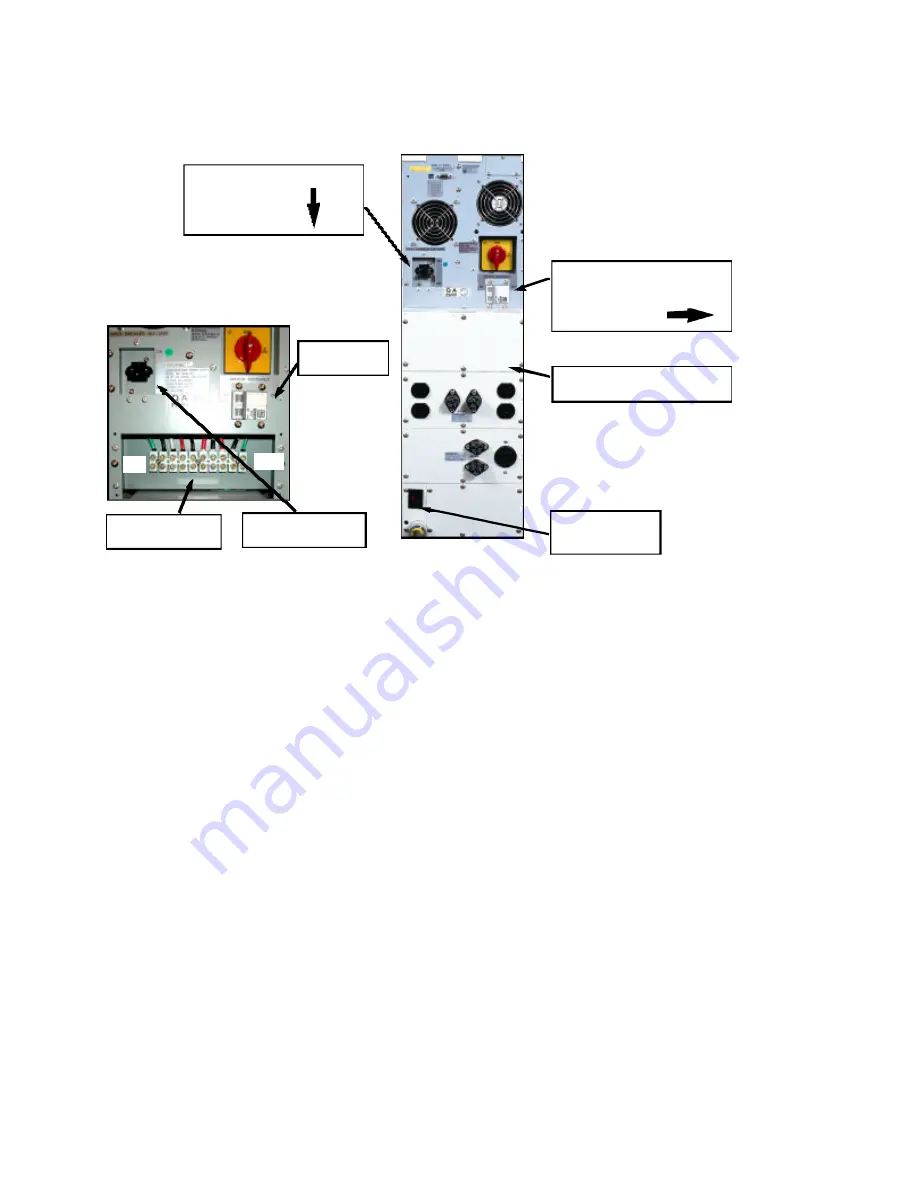
Verify the UPS has been turned off. Reference the picture below detailing a typical 
SG5-6kVA model rear panel and turn the battery disconnect circuit breaker to the 
“OFF” position. 

.

2.

Verify the UPS does not have any extended battery banks connected to the it. 
For models with a PDU, disconnect any cable connected to the extended battery 
connector. For hardwired models, verify no external hardwire connections are made

to 

terminals 4 & 5 of the hardwire terminal block. If connections are visible, locate the 
external battery cabinet(s) and turn the battery disconnect circuit breaker(s) to the 
“OFF” position in the same manner as the UPS in step 1.

3.

If the SG UPS model has an input line cord and plug, unplug the UPS plug from the 
utility outlet. For all other hardwire models, go to step 4.

4.

If the SG UPS model is a hardwire type, locate the building service panel and the 
circuit breaker that powers input to the UPS. Next,  turn the circuit breaker powering 
the UPS to the “OFF” position.

5.

To verify the UPS has been properly disconnected from all energy sources, return to 
the UPS and turn the UPS Input Power Switch to the up or “ON” position. 

THE UPS

SHOULD NOT POWER UP.

Next depress the button marked ON/OFF on the UPS 

front control panel, again 

THE UPS SHOULD NOT POWER UP

. Now turn the UPS

Input Power Switch, down or to the “OFF” position. 

If the UPS should power up upon performing any of the actions in this step, 
recheck steps 1 through 5 in an attempt to determine the AC or DC power 
source that is still  connected to the UPS. All power sources must be 
disconnected from the UPS and a successful completion of step 5 before 
continuing to step 6.

UPS Battery Disconnect

Circuit Breaker

“OFF” 

3

UPS Input Power Switch

“OFF” 

Extended Battery

Connector

REAR PANEL DETAIL FOR:

SG5K-1TXC

SG5K-2TC

SG5K-2TXC
SG6K-2TXC

(with PDU installed)

Power Distribution Unit

PDU

Hardwire Model View
SG5K-1TX, SG5K-2T

SG5K-2TX, SG6K-1TX

SG6K-2T, SG6K-2TX

Battery Circuit

Breaker

Hardwire Terminal

Block

Input Power

Switch

1

10

Summary of Contents for SG5K-1TX

Page 1: ...ormation 2004 Falcon Electric Inc All rights reserved All other brand names and trademarks are the property of their respective owners The information stated in this document is subject to change without notice 2004 02 05 Falcon Falcon Electric and UPS Plus logos are registered trademarks of Falcon Electric Inc FALCONElectric Inc 5116 Azusa Canyon Rd Irwindale California 91706 626 962 7770 Fax 626...

Page 2: ...r computer room environments the batteries should be replaced every three to five years In critical applications replace the batteries every two years When replacing the UPS batteries use the same number and type of batteries Exercise extreme caution when servicing the 240Vdc batteries in the UPS and External Battery Banks due to the risk of electrocution The batteries approved for the Falcon SG 5...

Page 3: ...ARE HANDLING AND RECYCLING OF SEALED LEAD ACID BATTERIES LIMITATION OF LIABILITY FALCON ELECTRIC INC ASSUMES NO LIABILITY FOR INCIDENTAL OR CONSEQUENTIAL LOSS OR DAMAGE DUE TO THE THIRD PARTY SERVICING OR REPLACEMENT OF BATTERIES IN FALCON PRODUCTS INCLUDING BUT NOT LIMITED TO LIABILITY FOR INJURY LOSS OF LIFE PROPERTY DAMAGE LOSS OF USE LOSS OF DATA LOSS OF TIME INCONVENIENCE OR COMMERCIAL LOSS O...

Page 4: ...that powers input to the UPS Next turn the circuit breaker powering the UPS to the OFF position 5 To verify the UPS has been properly disconnected from all energy sources return to the UPS and turn the UPS Input Power Switch to the up or ON position THE UPS SHOULD NOT POWER UP Next depress the button marked ON OFF on the UPS front control panel again THE UPS SHOULD NOT POWER UP Now turn the UPS In...

Page 5: ...move the side panel and set aside 8 The batteries are located on both sides of the UPS chassis Please take a few minutes to acquaint yourself with the positions of the batteries inside the UPS and the photos on the next page It is important to locate all of the battery and associated wiring locations prior to starting the battery removal installation process REMOVE ONE OF THE SHORT BATTERY INTERCO...

Page 6: ...Down Brackets Mounting Screws 3 Places Detail of the opposite end of the Battery Bracket secured by a screw shown with the screw removed Detail of Battery Bracket tab in slot mounting Batteries on right side of the UPS Additional batteries on the left side of the UPS BATT8 BATT7 BATT6 BATT5 BATT4 BATT3 BATT2 BATT1 BATT9 BATT10 BATT11 BATT12 BATT13 BATT14 BATT15 BATT16 BATT20 BATT19 BATT18 BATT17 M...

Page 7: ...tive terminal 13 Remove the long jumper wires from between the BATT5 negative and BATT4 positive terminals Also from between the BATT12 positive and BATT13 negative terminals 14 You are now ready to remove the old batteries from the chassis and install the new ones To avoid confusion when reinstalling the new batteries please take a few minutes to observe the positions of the old batteries prior t...

Page 8: ...BATT14 negative BATT14 positive to BATT15 negative BATT15 positive to BATT16 negative 22 Reinstall 1 of the long jumpers removed in step 13 from BATT13 negative to the BATT12 positive terminal Now reconnect the black wire coming from the right side BATT8 positive to the BATT13 negative terminal Connect the black jumper connected to the BATT17 negative terminal to the BATT16 positive terminal The l...

Page 9: ...PS is operating normally from the utility power source switch off the Battery Circuit Breaker located on the UPS rear panel Locate the BATT BATT terminals on the bottom of the main PSDR board see page 5 for the board location Using a Voltmeter set to the 300Vdc scale measure the battery charger voltage at these test points The voltage should be 274Vdc 2Vdc If this voltage is close but not within t...

Page 10: ...s removed in step 4 and tighten 35 If the UPS is model SG1K 1T reinstall the battery fuse and cap 36 Connect the UPS to an utility power source 37 Turn on the UPS power switch located on the rear panel The UPS should power up and function normally as defined in the Owner s Manual 38 Leave the UPS turned on for 24 hours to allow the batteries to fully charge 9 ...

Reviews: