


3.5 TEMPERATURE CONTROLLER
3.5.1 Fault Finding
There is no setting temperature adjustment available to
the user. Controller has been pre-programmed at factory
for a thermostat setting of 85°C. When switching power
ON to appliance, controller display will be going through
an initialisation process lasting a couple of seconds
before settling into its operating mode.
Under normal operation ambient chamber temperature at
controller probe location will be displayed. Once fully
pre-heated, chamber temperature will cycle around this
value as elements are switched ON/OFF to maintain set
temperature.
“Out1”
will illuminate green when elements
are energised.
Empty chamber cycle normally remains within 10° of this
setting. Refer to User Instructions for further performance
comments.
If
‘PR 1’
is flashing on display the probe or its electrical
connections are defective. Check integrity of probe wire
connections to controller before considering replacement.
Wire connections can either be accessed by removing
top panel as Section 3.1.1 or control panel as
Section 3.1.2.
Power ON neon going OFF for longer periods in
combination with wide temperature swings signifies
the thermal limiter is activated. Check thermostat setting
and whether controller is shorted out of circuit before
considering replacement.
To check pre-programmed thermostat setting, remove
outer control cover by undoing tamperproof screws.
Press controller
‘set’
button to check that pre-set
temperature is correct. Press
‘set’
again to return to
operational mode with display of ambient chamber
temperature. Replace outer control cover with
tamperproof screws provided.
3.5.2 To Replace Controller
Remove control panel as Section 3.1.2.
To remove controller, disconnect wires. Depress
locking tabs of mounting bracket at side of controller and
slide off to rear. Withdraw controller forward through
panel.
Re-fit in reverse order. Ensure mounting bracket locking
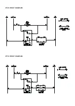
tabs are engaged. Refer to circuit diagram for correct
re-wiring.
3.5.3 To Replace Probe
Remove top panel as Section 3.1.1. Disconnect probe
connections at rear of controller. At probe end, carefully
lift away thermal insulation and undo chamber seal.
Probe sensor is fitted within the chamber compartment
roof divider channel. From inside chamber, undo probe
and guard fixings to feed out through roof aperture.
Re-fit in reverse order. Ensure roof probe is correctly
located. Re-seal at roof aperture and fully restored
thermal insulation on top of chamber before re-fitting top
panel. Check temperature controller operation.
3.6 THERMAL LIMITER
A self-resetting thermal limiter is fitted to the unit to
protect components from further damage should
controller operation fail while elements are energised.
To access device, remove top panel as Section 3.1.1.
Thermal limiter is attached to top of heating chamber.
To remove device, carefully lift thermal insulation in the
vicinity of limiter body. Pull off wire terminal connections
and undo mechanical fixings.
Re-fit in reverse order, applying heat sink compound
between limiter and chamber surfaces. After accessing
component, ensure thermal insulation is fully restored
before re-fitting top panel.
3.7 ELEMENTS
Remove element access panel as Section 3.1.3.
Pull off element terminal connections. Undo element tray
fixings. Slide tray out. Elements may now be removed.
Refit in reverse order, ensuring both electrical and
mechanical connections are securely fixed.
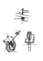
3.8 DOOR CATCH MECHANISM
Refer to
Figure 1
.
(Page 7)
To remove door stop spring mechanism, tee-bar must be
fully unscrewed. Depress door stop to bring tee-bar down
below mounting plate edge. Unscrew tee-bar. Door stop
mechanism can then be withdrawn and spring and
washer removed. When replacing, ensure washer is
located below the spring against base.
To remove foot pedal and mounting plate, first unscrew
tee-bar sufficiently to clear mounting plate. Undo fixings
on underside of base. Refit in reverse order.
Adjust tee-bar as required to ensure satisfactory door
operation. Door stop engages with roller attached to
bottom edge of door.
5