29
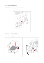
7.5.2 Remove two hex screws from each side of underside of the hob. Pull back pin and
remove element head end covers from the topside of hob and repeat on opposite side
if required.
7.5.3 Disconnect the wires from micro switch and unfasten two cap screws to remove micro
switch.
7.6 HEATING ELEMENTS REMOVAL
7.6.1 Remove splashguard, rear panel and element head end covers as shown in section
7.5.1 and 7.5.2.
7.6.2 Remove control panel as shown in section 7.2.1.
7.6.3 Remove element wires from contactor(s).
7.6.4 Remove three hex nuts on each end of the element mounting plates. E9490 version
will require the centre pillar nuts to be removed.
Summary of Contents for E9460
Page 18: ...18 6 0 INSTALLATION ELECTRICAL SAFETY AND ADVICE REGARDING SUPPLEMENTARY ELECTRICAL PROTECTION...
Page 31: ...31 7 7 CIRCUIT DIAGRAMS 7 7 1 E9490 Circuit Diagram...
Page 32: ...32 7 7 2 E9460 Circuit Diagram...
Page 33: ...33 7 8 WIRING DIAGRAMS 7 8 1 E9490 Wiring Diagram...
Page 34: ...34 7 8 2 E9460 Wiring Diagram...


