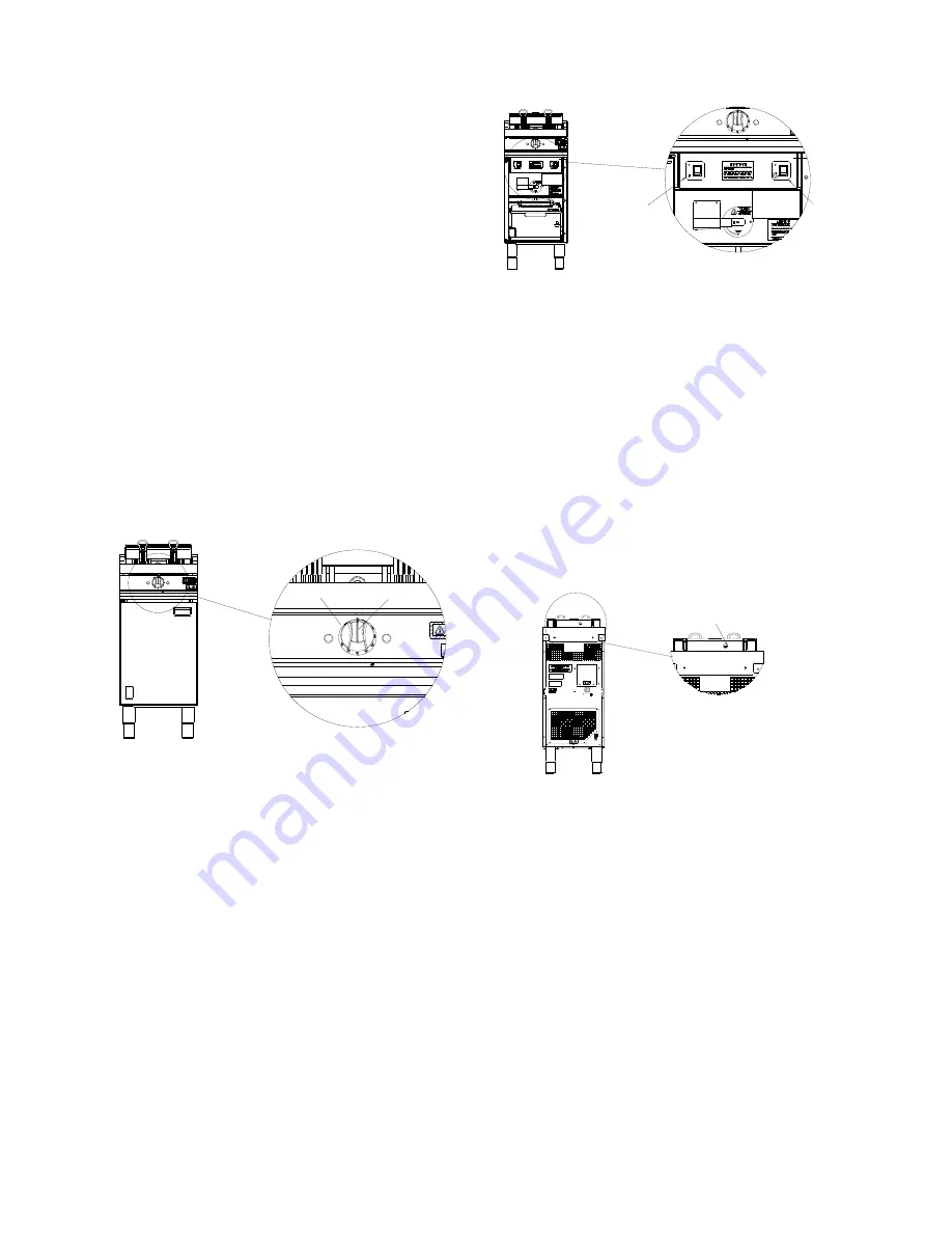
2.3.2 E3840 / E3840F - Additional Controls
Figure 3 – E3840 / 3840F - Additional Controls
The following additional controls are located behind
cabinet door.
1. Fryer ON/OFF Switch
Cuts power to appliance.
2. Filtration Pump Switch
(F model only)
Energises filtration pump.
3. Temperature Safety Limiter Reset Button
Located on rear of element box, below black dust cap,
refer to Figure 4.
Figure 4
2.3.3 E3840 and E3840F Controller Diagnostic
Indicators
(Refer to Control Panel Wiring
Diagram Page 11)
Green LED ‘ON’ indicates heat demand.
Green LED ‘OFF’ indicates no heat demand.
Red LED flashes if temperature probe is either short or
open circuited.
Red LED is permanently ‘ON’ to indicate system is OK.
Set point is +/-7
⁰
C of mid-set point.
SECTION 2 - ASSEMBLY and
COMMISSIONING
The electrical cable must be connected in accordance
with the various regulations listed on the cover of this
manual.
2.1 ASSEMBLY
a) Unpack appliance
b) Unpack fryer baskets and accessories.
c) Place element guard and baskets in pan.
d) Level appliance and fit all service protection kits.
(Anti-tilt kit, if ordered as accessory)
.
2.2 CONNECTION TO AN ELECTRICAL SUPPLY
The supply cable must be connected to a suitable
isolator switch as follows:
Phase 1: Brown, Phase 2: Black, Phase 3: Grey
Neutral: Blue, Earth: Green/Yellow
2.3 STARTING UP
2.3.1 E3840 / E3840F Fryer Control Panel
Figure 2 – E3840 / E3840F Control Panel
1. ON/OFF and Temperature Control Knob
Temperature Selection
(140 - 190°C). (Unit is off when in
position indicated).
2. Fat Melt Position
Feature for slow pulsed heating of solid fats.
3. Power on indicator.
4. Heat Demand Indicator
illuminates when thermostat demands heat, i.e. oil
temperature is more than 5
⁰
C below temperature setting.
Extinguishes when desired temperature is reached.
4
1
2
3
3
1
2
4
Summary of Contents for E3840
Page 16: ...16...


