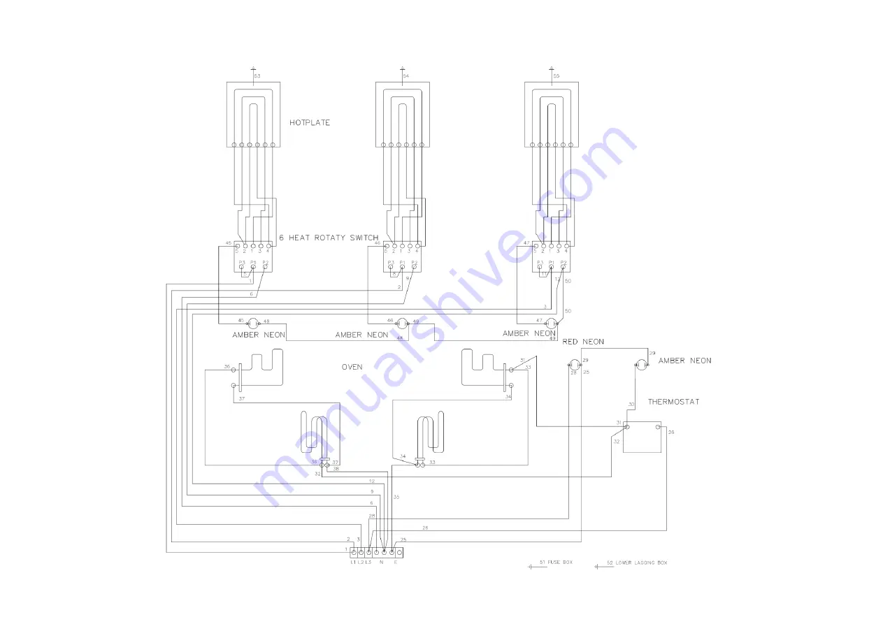
E1006 THREE HOTPLATE RANGE – WIRING DIAGRAM 3N~
Page 1: ...he operation and cleaning of the appliance IT IS MOST IMPORTANT THAT THESE INSTRUCTIONS BE CONSULTED BEFORE INSTALLING AND COMMISSIONING THIS APPLIANCE FAILURE TO COMPLY WITH THE SPECIFIED PROCEDURES...
Page 2: ...s Poor combustion caused by lack of cleaning Lubrication of moving parts Lubrication of gas cocks Cleaning adjustment of pilots Correction of gas pressure to appliance Renewing of electric cable ends...
Page 3: ...appliance be required to be positioned closer than 150mm 1 3 ELECTRICITY SUPPLY These appliances are suitable for AC supplies only On the range the standard terminal arrangement is for 3 phase 4 wire...
Page 4: ...ed from element chamber Replace all parts in reverse order 3 Check top plates are correctly located upon support pins 4 Make electrical connection via conduit entry at centre rear of unit 5 A pot rack...
Page 5: ...d pull forward 3 1 5 RH Outer Panel Remove fixings which secure panel bottom flange to underside of base Slide panel back approximately 25mm to withdraw two pins which locate into rear of corner post...
Page 6: ...enamelled oven back lining lift upward and also insulation cover panel lift upward and insulation pad Each assembly is secured by three fixings one through bracket where element passes through front...
Page 7: ...E1006 THREE HOTPLATE RANGE WIRING DIAGRAM 3N...
Page 8: ...E1026 THREE HOTPLATE BOILING TABLE WIRING DIAGRAM 3N...