background image

INSTALLATION

Check the appliance is electrically safe and gas sound when you have finished.

21

130 mm min

800 mm

912 mm

min

937 mm

min

75 mm

min

75 mm

min

minimum

Fig.7-1

Fig.7-3

Fig.7-4

410 mm

min

1092 mm min* 

**

Fig.7-2

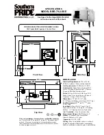
Positioning the Cooker

Fig.7-1

 shows the minimum recommended distance from the 

cooker to nearby surfaces.
The cooker should not be placed on a base.
Above hotplate surround should be level with, or above, any 

adjacent work surface.
A gap of 75 mm should be left between each side of the 

cooker 

ABOVE 

the hotplate level and any adjacent vertical 

surface.
For non-combustible surfaces (such as unpainted metal or 

ceramic tiles), this can be reduced to 25 mm.
A minimum space of 800 mm is required between the top of 

the hotplate and a horizontal combustible surface.

Fig.7-2

 shows the suggested clearances above the cooker.

*Any cookerhood should be installed in accordance with the 

hood manufacturer’s instructions.
**Any splashback must be fitted in accordance with the 

manufacturers instructions.  Allowance should be made for the 

flue trim, which is fitted to the cooker hob.

Surfaces of furniture and walls at the sides and rear of the 

appliance should be heat, splash and steam resistant. Certain 

types of vinyl or laminate kitchen furniture are particularly 

prone to heat damage and discolouration.
We cannot accept responsibility for damage caused by 

normal use of the cooker to any material that de-laminates 

or discolours at temperatures less than 65 °C above room 

temperature
We recommend a gap of 1102 mm between units to allow 

for moving the cooker. DO NOT box the cooker in: it must 

be possible to move the cooker in and out for cleaning and 

servicing.
A clearance of 130 mm is required if the cooker is near a 

corner of the kitchen to allow the oven doors to open  

(Fig.7-3)

. The actual opening of the doors is slightly less but 

this allows for some protection of your hand as you open the 

door.

Moving the Cooker

n

n

On no account try and move the cooker while it is 

plugged into the electricity supply.

n

n

The cooker is very heavy, so take great care.

We recommend that two people manoeuvre the cooker. 

Make sure that the floor covering is firmly fixed, or removed, 

to prevent it being disturbed when moving the cooker 

around.
To help you, there are two levelling rollers at the back, and 

two screw-down levelling feet at the front.
Remove the polystyrene base pack. From the front, tilt 

the cooker backwards and remove the front half of the 

polystyrene base 

(Fig.7-4)

. Repeat from the back and remove 

the rear half of the polystyrene base.

Summary of Contents for 1092 CKR

Page 1: ...1092 CT Dual Fuel USER GUIDE INSTALLATION INSTRUCTIONS...

Page 2: ...for a fan oven orgas mark 7 2 Pull the small sprigs off the rosemary branches and set aside with the garlic 2 Using the tip of a paring knife make up to 20 well spaced cuts into the flesh of the lamb...

Page 3: ...ain Top 13 French Cooktop 13 Glide out grill 14 Ovens 15 Cleaning Table 16 6 Troubleshooting 17 7 Installation 19 Dear Installer 19 Safety Requirements and Regulations 19 Provision of Ventilation 19 L...

Page 4: ...ii...

Page 5: ...oor open Make sure the room is well ventilated to the outside air see Ventilation below People with respiratory or allergy problems should vacate the area for this brief period If You Smell Gas Do not...

Page 6: ...dangerous and may result in fire n n NEVER leave a chip pan unattended Always heat fat slowly and watch as it heats Deep fry pans should be only one third full of fat Filling the pan too full of fat c...

Page 7: ...low of gas if the flame goes out When a hotplate control knob is pressed in sparks will be made at every burner this is normal DO NOT attempt to disassemble or clean around any burner while another bu...

Page 8: ...The maximum allowable pan base diameter is 260 mm DO NOT use cooking vessels on the hotplate that overlap the edges The French Cooktop This is the cooking element preferred by professionals because o...

Page 9: ...the right hand half Adjust the heat to suit by turning the knob To heat the whole grill turn the knob clockwise Fig 2 10 To heat the right hand half turn the knob counter clockwise Fig 2 11 The neon i...

Page 10: ...t the top of the oven than at the base as in Fan Assisted Oven function Similar items being cooked will need to be swapped around for even cooking This means that foods requiring different temperature...

Page 11: ...function selector control to a cooking function Fig 2 14 shows the control set for convectional oven cooking Turn the oven temperature knob to the temperature required Fig 2 15 The oven indicator lig...

Page 12: ...ons The oven shelves are retained when pulled forward but can be easily removed and refitted To Remove and Refit the Shelf The shelf has a small kink on either side Fig 2 19 To remove the shelf line t...

Page 13: ...e drawer will open Push the ends of the plastic clips down on the left hand side up on the right hand side to release the catches holding the drawer to the side rails Fig 2 22 At the same time pull th...

Page 14: ...the maximum recommended size of a baking tray is 340mm 13 by 340mm 13 When the oven is on do not leave the door open for longer than necessary otherwise the knobs may get very hot Always leave a fing...

Page 15: ...0 minutes according to size 2 3 hours 45 60 minutes 40 45 minutes 2 to 3 hours 20 30 minutes 15 20 minutes 15 20 minutes per 500g Steaks according to thickness Conventional Oven Temperature C Shelf Po...

Page 16: ...icult to remove later n n Make sure the flow of combustion and ventilation air to the cooker is unobstructed for example by build up of fats or grease On Natural Gas the burners flames should be a blu...

Page 17: ...reful to avoid steam burns Some cleaners can produce noxious fumes if applied to a hot surface Always clean the cooktop after use It should only be cleaned with a soft cloth wrung out in clean hot soa...

Page 18: ...he telescopic runners to allow cleaning of the grill chamber first remove the grill tray then you can unhook them from the grill chamber sides Fig 5 9 Wipe the sides clean with a soft cloth and mild d...

Page 19: ...This will ensure that the panels are working effectively n n Do not use steel wool or any other materials that will scratch the surface n n Do not use oven cleaning pads The Oven Shelf Supports The sh...

Page 20: ...inted surface Hot soapy water soft cloth Splashback rear grille Enamel or stainless steel Hot soapy water soft cloth Cream cleaner with care if necessary Control panel Paint enamel or stainless steel...

Page 21: ...t my original installer to come back to fix it who pays You do Service organizations will charge for their call outs if they are correcting work carried out by your original installer It is in your in...

Page 22: ...line of hinge pin The oven door is misaligned The bottom hinge of either oven door can be adjusted to alter the angle of the door Fig 6 1 Loosen the bottom hinge fixing screws and use the notch and a...

Page 23: ...n and Use regulations The relevant Building IEE regulations In the Republic of Ireland the cooker must be installed in accordance with The installation must be carried out by a competent person and in...

Page 24: ...priate area of the data badge this will identify the gas type for which the appliance is now set You will need the following equipment to complete the cooker installation satisfactorily Stability brac...

Page 25: ...lash and steam resistant Certain types of vinyl or laminate kitchen furniture are particularly prone to heat damage and discolouration We cannot accept responsibility for damage caused by normal use o...

Page 26: ...s to manoeuvre the cooker Fitting a Stability Bracket Floor Fixing Assemble the parts Fig 7 7 Using suitable screws and fixings attach the assembled bracket to the floor to give a minimum engagement o...

Page 27: ...ses may be purchased at most builders merchants The gas supply needs to terminate with a down facing bayonet The connector is located just below the hotplate level at the rear of the cooker If in doub...

Page 28: ...ed Earth Leakage Breakers The combined use of your cooker and other domestic appliances may cause nuisance tripping so we recommend that the cooker is protected on an individual RCD Residual Current D...

Page 29: ...Check that the oven fans start to turn and that the ovens start to heat up Turn off the oven Final Fitting Fitting the Plinth Loosen the 3 screws along the front bottom edge of the cooker Hook the ce...

Page 30: ...s First remove the service plate Either Use a long box spanner to access and remove the old jets Or Lift up the front of the hotplate top and prop it up to access the burner bases Remove the old jets...

Page 31: ...ers with the venturi tubes and evenly tighten Refit the burner heads making sure they are reassembled in the correct way on the burner bodies Fig 8 6 Refit the pan supports Reassemble in the reverse o...

Page 32: ...The ratings are for 230 V 50 Hz Code Colour b Blue br Brown bk Black or Orange r Red v Violet w White y Yellow g y Green yellow gr Grey Code Description D1 Right hand oven thermostat D2 Right hand ov...

Page 33: ...40 3 0 kW 120 3 0 kW 214 g h 82 Right hand front burner 32 1 0 kW 95 1 0 kW 121 g h 64 This is a special non counterbored jet it is NOT the same as the 95 jet used in the right hand front natural gas...

Page 34: ...30 Notes...

Page 35: ...een repaired by persons or organisations other than those authorised to act on behalf of AGA Rangemaster Exceptions Items not included under the free 3 year guarantee include pan supports griddles wok...

Page 36: ...fication design and production of products and thus alterations take place periodically Whilst every effort is made to produce up to date literature this booklet should not be regarded as an infallibl...

Reviews: