


Pneumatic Connections
Clean all pipelines to remove dirt and scale before installa
tion.
Apply a minimum amount of pipe compound to the male
threads of the air line only.
Do not use teflon tape as a
sealant.
Start with the third thread back and work away
from the end of the fitting to avoid contaminating the
transducer.
The inlet and outlet ports are labeled on the ends of the
transducer. Tighten all connections securely. Avoid
undersized fittings that will limit the flow through the
transducer. For more information, see Figure 2.
NOTE: Instrument quality air, per ISAStandards S7.3
1981, is required. Use a filter to remove dirt
and liquid in the air line ahead of the trans
ducer. If an air line lubricator is used, it MUST
be located downstream to avoid interference
with transducer performance.
The user is responsible for ensuring that the
environment in which the unit is installed and
the operating gas are compatible with the
materials in the transducer.
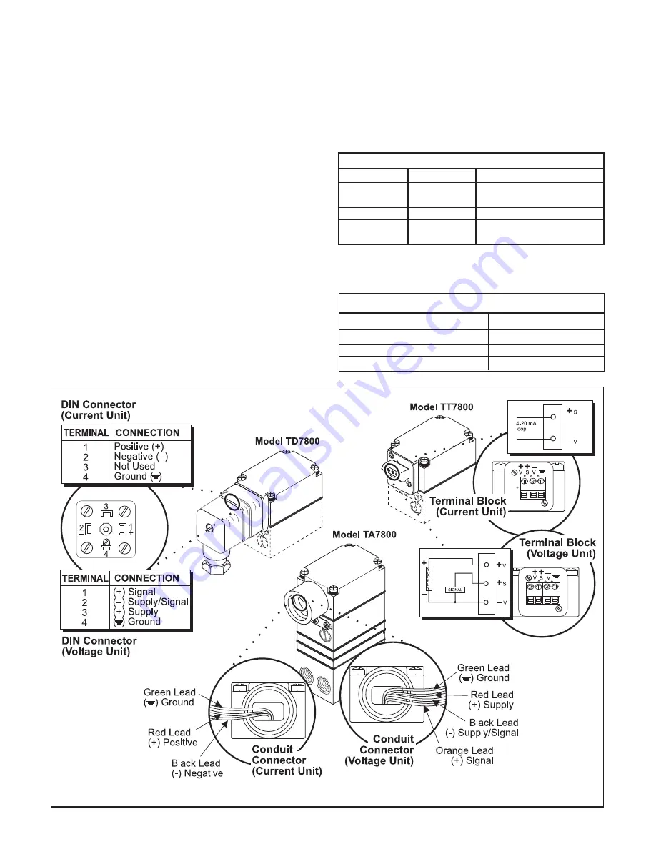
Electrical Connections
Make connections to the Terminal Block, Conduit Connec
tor or the DIN Connector as shown in Figure 9.
Wiring in Hazardous Areas
Wiring in hazardous areas should comply with the codes
in Table 1 and with any local codes that apply.
Table 1.
Hazardous Location Wiring Practices
Country
Agency
Code
U.S.
FM
ANSI/ISA RP 12.6
ANSI/NFPA 70
Canada
CSA
CED Part 1
Europe
ATEX
EN 50 039, EN 60079-14,
IEC 60079-14
Intrinsically Safe Connections
For more information, see the latest revisions of the draw
ings listed in Table 2.
Table 2.
Intrinsically Safe Connections
Underwriting Group
Drawing Number
FM (Factory Mutual)
EC-18970
CSA (Canadian Standards)
EC-18971
ATEX
EC-18972
Figure 9.
Electrical Connections
6


