background image

INSTALLATION

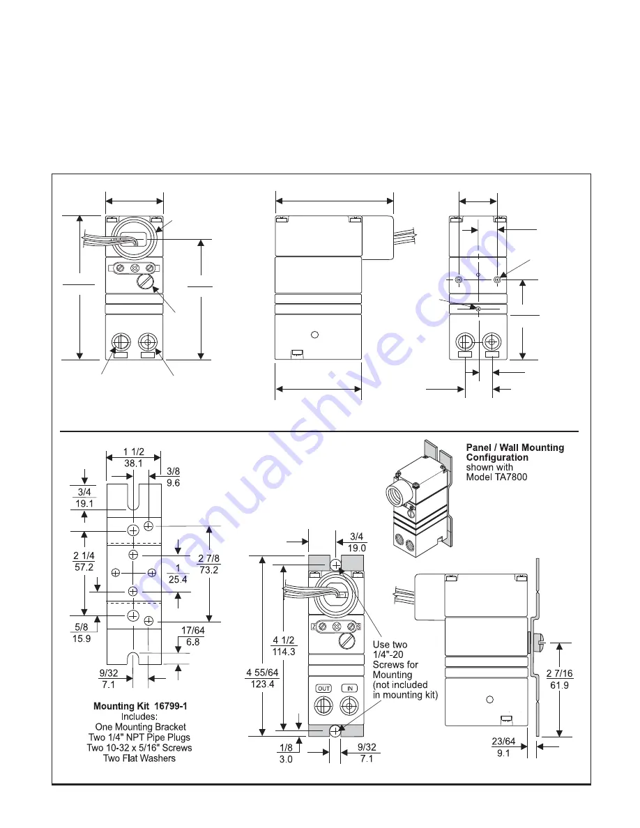
You can mount the Model T7800 on a flat surface using two 
10-32 Screws.  For more information, see Figure 2. 

The Model T7800 ships from the factory with Mounting Kit 
16799-1 for Panel or Wall Mounting and Mounting Bracket 
Kit 16893-1 for Din Rail Mounting.  For more information, see 
Figure 3 and Figure 7. 

An optional mounting kit, 19254-1,  is available to install the 
unit on a 2" pipe.  For more information, see Figure 8. 

ATEX Directive- Special Conditions for Safe Use 

The enclosure is manufactured from aluminum alloy. In rare 
cases, igntion sources due to impact and friction sparks 
could occur.  This shall be considered when the equipment 
is installed in locations that specifically require Group II, 
category 1G equipment. 

NOTE:  The TR7800 transducer is designed for use 

with the TR Rack Kit.  Physically, it is the same 
as the TT7800 (Terminal Block) unit except 
that the terminal block has been rotated to the 
back.  For more information, see Figure  6. 

1/2-14 

NPT 

OUT 

Z


IN 

S


3 23/32 

94.5 

3 5/32 

80.3 

1/2 

12.7 

25/32 

19.7 

25/64 

9.8 

25.4 

OUT 

IN 

2 3/64 

51.8 

Use two 
10-32 
Screws for 
mounting 

3 3/64 

77.5 

2 1/4 

57.1 

1 33/64 

38.7 

Orifice 

Inlet

Outlet 

Vent 

Figure  3. 

Mounting Kit 16799-1

 (included with unit) 

Figure 2. 

TA7800 Outline Dimensions 

3

Summary of Contents for T7800 Series

Page 1: ...DC input signal to a linearly proportional pneumatic output pressure SPECIFICATIONS Minimum Span 3 15 0 2 1 0 20 100 4 20 mA DC 0 10 VDC 1 9 VDC 0 5 VDC 1 5 VDC 20 120 1 5 8 0 150 800 5 0 35 35 3 27...

Page 2: ...ltage input units TDFI7800 TAFI7800 TDFN7800 TAFN7800 Class I Division 2 Groups A B C and D Class II Division 2 Groups F and G Class III Division 2 NEMA 4X Enclosure Temperature Code T4 TTFI7800 TRFI7...

Page 3: ...umalloy Inrare cases igntion sources due to impact and friction sparks couldoccur Thisshallbeconsideredwhentheequipment is installed in locations that specifically require Group II category1Gequipment...

Page 4: ...Installation continued Figure 6 TR7800 Outline Dimensions Figure 5 TD7800 Outline Dimensions Figure 4 TT7800 Outline Dimensions 4...

Page 5: ...Figure 8 Optional Mounting Kit 19254 1 sold separately Figure 7 Din Rail Mounting Kit 16893 1 included with unit 5...

Page 6: ...tream to avoid interference with transducer performance The user is responsible for ensuring that the environmentinwhichtheunit isinstalledand the operating gas are compatible with the materials in th...

Page 7: ...desiredoutputrangeis obtained SPLIT RANGEOPERATION Lo Hi Span Adjustment 1 Set the Lo Hi Span switch to the Lo position for 3 9 psig or 9 15 psig output range and for 4 20 mA input range Set the Lo Hi...

Page 8: ...Calibrations Adjustments continued Figure 10 T7800CalibrationConfiguration 8...

Page 9: ...11 1 12 1 13 14 15 16 17 1 18 19 Qty Cover Machining Screw Screw Gasket Nozzle Body Assembly Orifice Assembly Spring Disk Diaphragm Spacer Ring Diaphragm Assembly Foam Block Valve Body Assembly Screw...

Page 10: ...n with alcohol and dry with compressed air NOTES 1 Parts must be completely dry before reassembling 2 If the standard maintenance procedure does not correct the problem install the appropriate service...

Reviews: