


8
fagorindustrial.com
2.5
Installation and assembly
Units represented in this manual are intended for indoor use only. Be sure the
location chosen has a floor strong enough to support the total weight of the
unit and contents. For the most efficient operation, be sure to provide good air
circulation inside and outside of the unit.
INSIDE CABINET
The first cleaning must be made when you unpack the unit and before switching it
on. Clean it with water and a mild detergent. When it is clean and dry, insert the
accessories in the appropriate places, for the best use of the user.
OUTSIDE CABINET
Be sure the unit has good air circulation around it. Avoid hot corners and
locations near stoves and ovens. It is recommended the unit be installed no
closer than 2” from any wall. The place where the refrigerator is placed must be
open and clean, avoiding that de fan of the condensing unit absorbs materials
which are deposited then into the condenser blades and coil, which can produce
failures.
The unit should not be installed under ambient temperatures higher than 100 °F.
If the relative humidity is higher than 60 %, the door frames may sweat water. This
is not a malfunctioning of the unit.
2.6
Connections (electrical)
Refer to the amperage data in this manual or on data plate and your local code
or the National Electrical Code to be sure unit is connected to the proper power
source. Verify correct incoming voltage according to the Data Plate information.
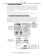
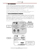
The data plate in located inside the unit, near the top front left corner. Under
any circumstances should the data plate be removed from the unit.
The data plate is essential to identify the particular features of your unit and is
of great benefit to installers, operators and maintenance personnel. It is
recommended that, in the event the data plate is removed, you copy down the
essential information in this manual for reference before installation.
A protected circuit of the correct voltage and amperage must be run for
connection of the supply cord. Unit must be grounded and connected in
accordance with NEC Article 422 Appliances.
OPERATION
3.1 General information.
3.2 Control panel description.
3.3 Machine settings and programs.
3.1
General information
Good air flow inside the cabinet is critical. Do not block air flow to the fans.
Allow three inches of space along the front, back, and sides.
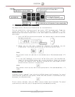
3.2
Control panel description
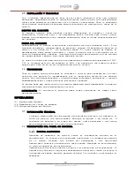
3.2.1
Electronic Control
After connecting your unit, turn ON rocker switch located next to the
controller. The display will light up showing the temperature inside the
unit. Also, the compressor and fan icons will flash for a period of three
minutes. After this delay the unit will start cooling.
Verify you don't have any alarms on the temperature controller. If after
you turn ON the equipment the controller shows the alarm icon or an error
code, call for technical service. They will help you fix the problem.


