


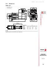


3-phase servomotors. FKM
3.
3-
PHASE SERVOM
O
TORS. FKM
Axial an
d radia
l load
s on
the
sha
ft exte
nsio
n
172
· 164 ·
Ref.2105
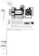
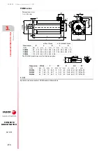
FXM|FKM
SERVOMOTOR
3.11
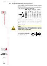
Axial and radial loads on the shaft extension
The following table shows the maximum axial and radial forces that the shaft
extension can withstand:
*
E
, length in mm of the shaft end on FKM9 servomotors. See dimension
according to model in the dimensions drawing.
Note
. When applying a combined axis and radial load, decrease the
maximum radial force allowed “Fr” to 70 % of the value indicated in the
table.
Also bear in mind that:
T- 3/68
Maximum values for axial and radial loads.
Series
Axial force
·
Fax
·
Radial force
·
Fr
·
Distance
·
d
·
Units
N
lbf
N
lbf
mm
in
FKM1
45
10.11 234
52.60 8.75
0.34
FKM2
125 28.10 668 150.17
20
0.78
FKM4
140 31.47 737 165.68
25
0.98
FKM6
240 53.95 1342 301.69
29
1.14
FKM8
440 98.91 1616 363.29
40
1.57
FKM9
339 76.21 1775 399.03
E
/2
* E
/50.8
*
Fax
Fr
d
WARNING.
Avoid hitting the servomotor and especially its shaft when installing
transmission pulleys or gear boxes. These servomotors have extremely
fragile optical and electronic components.
Use some tool that is supported in
the threaded hole on the shaft to
insert the pulley or the gear!


