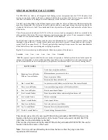


SELF DIAGNOSTIC FAULT CODES
The FEB-20E has a built in self diagnostic fault finding system incorporated into the P.C.B. Should a fault
develop on the boiler which could cause a situation liable for the operation of the boiler to become unsafe, then
the boiler will fail safe by locking-out which is displayed via the 'red neon' on the control panel.
The fault can be identified by the different sequences in which the 'red neon' flashes and the duration that the
neon stays illuminated. The electronic fail safe is also backed by a mechanical means of protection, should the
electronics fail to detect a fault. These mechanical forms of protection will protect and ensure the safe shut down
of the boiler.
The software protection built into the P.C.B. will run a system check on components which are essential to the
safe operation of the boiler. This occurs before
any ignition sequence takes place. If any component is found to
be faulty or out of a predetermined range, then lock-out will be displayed.
Each fault code begins and finishes with the 'red neon' illuminated for 5 seconds, the relevant fault is then
indicated by the number of 1 second flashes which occur between the initial 5 second flash and the closing 5
second flash. These range from 0 - 12. Please be patient when counting the sequence as the correct identification
of the fault will save time on isolating and rectifying the problem.
Eg:
Fault 6 water overheating would display the following sequence of the red neon;
5 seconds
1 sec
1 sec
1 sec
1 sec
1 sec
1 sec
5 seconds
N.B.
The sequence repeats until either the reset button is depressed or the fault rectified. Some faults require the
component temperature to return within operating range before reset, is possible also some sequences may take
up to 3 minutes before lock-out is displayed, e.g. air pressure switch failure fault 1 or water over heating fault 6.
FAULT CODES
FAULT
Lack of gas or ignition problems
Minimum burner pressure set to low
Flame supervision failure
0
Repeating 5 second flashes
With no 1 second flashes
Burner on but flame indicator off
1
One 1 second flash
Air pressure switch failure, crossed tubes or flue venturi blocked
3
Three 1 second flashes
Low central heating pressure or Hi-limit stat failure
4
Four 1 second flashes
Printed circuit board failure
5
Five 1 second flashes
Flame supervision failure, indicator light on burner off
6
Six 1 second flashes
Water overheating
7
Seven 1 second flashes
C
ontrol panel failure
9
Nine 1 second flashes
Gas valve control circuit failure
10
Ten 1 second flashes
Domestic hot water thermistor failure
12
Twelve 1 second flashes
Central heating thermistor failure
These fault codes are for the new type PCB with the part number MU0870700, this can be
found on the bottom right hand corner of the board. You can also easily identify this PCB
which has two blue transformers attached.
This is a direct replacement for the older PCB with the part number MU0868700, this can be
found on the bottom centre of the board.
Note:
Fan wire will need threading down from the fan to allow the plug to reach the
repositioned J10 terminal.


