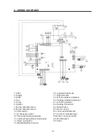
Fagor FEB-20E UK ECOPLUS User Instructions Download Page 19

19

6.6 FINAL CHECKS

- Re-light and test for gas soundness

- Set the C.H. and D.H.W. temperature selectors to the required settings.

- Ensure that the time clock and/or room stat (if fitted) are set to the required setting (s).

6.7 USER’S INSTRUCTIONS

Upon completion of  testing the system, the installer should:

-  Give the ‘users Instructions’ to the owner and emphasise their responsibilities under the “Gas Safety
(Installation and Use)  Regulations 1998”

-  Explain and demonstrate the lighting and shut down  procedures.

-  Advise the owner on the efficient use of the  system, including the use and adjustment of all system con-
trols for both D.H.W. and C.H.

- Advise the user of the precautions necessary to prevent damage to the system, and to the building,  in the
event of the system remaining inoperative  during frost conditions.

-  Explain the function of the boiler lock-out devices, and  how to reset it.  Emphasise that if cut - out persists,
the boiler should be turned off and the installer or service engineer consulted.

-  Stress the importance of an annual service by a Corgi registered heating engineer.

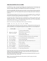
To ensure continued efficient operation of the appliance, it is recommended that it is checked and serviced
as necessary at regular intervals.  The frequency of servicing will depend upon the particular installation con-
ditions and usage but in general once a year should be adequate.

It is the law that any service work must be carried out by  registered personnel (C.O.R.G.I.).

Before commencing any service operation, ISOLATE the mains electric supply, and TURN OFF the gas sup-
ply at the  main service cock.  Service the appliance by following the full procedure detailed below.

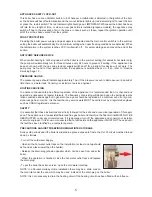
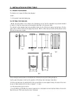
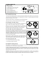
MINIMUM CLEARANCE REQUIRED FOR SERVICING AND REPLACEMENT OF PARTS

*  

Distance at the side

The minimum distance necessary for carrying out maintenance operations,  is 5 mm

*

Distance at the top

The minimum distance necessary for carrying out maintenance operations, is 200mm

Distance at the bottom

The minimum distance necessary for carrying out maintenance operations, is 250 mm.

Distance at the front

The minimum distance necessary for access during maintenance opera-
tions, is 250mm, although this distance may be reduced to 5 mm, as long
as a door is installed which can be removed when it comes to carrying out
maintenance work.

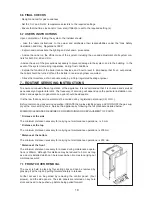
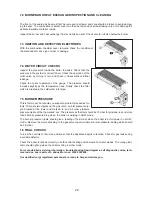
7.1 FRONT COVER REMOVAL

The cover is held in place by four spring clips and can be removed by
grasping it at the top and pulling forward sharply to release.

Further access can be gained by removing the control panel. (Four
screws),  and the side panels.  The side panels are retained on key hole
slots and need to be pushed up before being pulled forward.

7.- ROUTINE SERVICING INSTRUCTIONS

Summary of Contents for FEB-20E UK ECOPLUS

Page 1: ...FEB 20E UK ECOPLUS USER INSTRUCTIONS AND TECHNICAL INSTRUCTIONS...

Page 2: ...STRUCTIONS 3 2 GENERAL SPECIFICATIONS 6 3 TECHNICAL DATA 9 4 GENERAL INSTALLATION REQUIREMENTS 10 5 INSTALLATION INSTRUCTIONS 14 6 COMMISSIONING INSTRUCTIONS 17 7 ROUTINE SERVING INSTRUCTIONS 19 8 WIR...

Page 3: ...ELIMINARY WARNINGS Check all of the gas pipe joints and make sure that gas reaches the boiler with the gas cock turned on Make sure that the central heating circuit is completely full and vented The p...

Page 4: ...of simple mixer showers it is wise to turn the temperature selector down on the boiler before using the shower If a tap or shower head is too restrictive due to a fault or blockage the flow rate will...

Page 5: ...engineer ROUTINE SERVICING To ensure continued safe and efficient operation of the appliance it is recommended that it is checked and serviced as necessary at regular intervals The frequency of servi...

Page 6: ...bustion air Modulating gas valve with double safety valves Circulation pump with manual anti seizure device and speed selector Central heating expansion vessel Differential air pressure switch only al...

Page 7: ...limit stat 6 Ionisation electrode 7 Main Burner 8 Circulation Pump 9 Flow switch 10 Pressure relief valve 11 Fan 12 Heat Exchanger 13 Combustion Chamber 14 Expansion Vessel 15 Ignition electrode 16 D...

Page 8: ...lectrode 5 Burner 6 Injector Manifold 7 D H W Thermistor 8 Burner pressure nipple 9 Gas valve 10 Inlet pressure nipple 11 Gas inlet 13 D H W outlet 14 Heating flow 16 Flow switch 17 Water filter 18 Co...

Page 9: ...6 D H W Nominal Flow l min 10 Minimum Flow Rate Required to Activate D H W Mode l min 2 Maximum C H 3 Maximum D H W 10 Operating Pressure bar Minimum D H W 0 25 Expansion Vessel Capacity l 7 Central...

Page 10: ...in any way as over riding statutory obligations 4 2 BOILER LOCATION In positioning the boiler the following limitations MUST be observed The position MUST allow for a suitable flue termination to be m...

Page 11: ...rt of the terminal is fitted less that 2M 78 in above ground above a balcony or above a flat roof to which people have access the terminal MUST be protected by a purpose designed guard In certain weat...

Page 12: ...should be 3A This connection should be readily accessible and be made adjacent to the boiler 4 6 GAS SUPPLY A Propane gas supply at 37m bar is required Ensure the regulator is of sufficient capacity...

Page 13: ...hin the prescribed limits refer to technical data page 7 If neces sary a pressure reducing valve should be fitted to the mains supply before D H W inlet connection The DHW performance is summarised in...

Page 14: ...about 6mm should be allowed on the flue pipe to stop water ingress A screw fixing should be made on the bottom rail of the boiler to secure it during transport Use the paper template to mark out the...

Page 15: ...closed Any 24V controls may be used but gold contacts are recommended DO NOT under any circumstances use a mains supply to the stat as you will blow the P C B in the boiler Only voltage free switching...

Page 16: ...the available length by 0 8m See installation examples It is recommendable to fit the pipe at a slight 2 or 3 downwards incline to prevent any water or condensa tion from entering in the boiler Where...

Page 17: ...boiler is fitted with an automatic air vent Check that the cap found on the top left surface of the boiler is loose In order to fill the installation correctly the following sequence must be followed...

Page 18: ...e boiler is ready to supply it giving priority to the D H W with the central heating on standby until the D H W demand ceases 6 5 4 Turning the boiler off Turn the main control switch to the O setting...

Page 19: ...ency of servicing will depend upon the particular installation con ditions and usage but in general once a year should be adequate It is the law that any service work must be carried out by registered...

Page 20: ...BURNER PRESSURE This is factory set but should you suspect a problem proceed as fol lows There are two nipples on the gas valve an inlet pressure nip ple situated at the lower end marked in and a bur...

Page 21: ...alve 2 10 Flow switch 11 Air pressure switch 12 Room thermostat optional 13 Terminal block Room thermostat 14 Clock connection 15 Modulating Electro valve 16 Ionisation electrode 17 High limit stat 19...

Page 22: ...equence of the red neon 5 seconds 1 sec 1 sec 1 sec 1 sec 1 sec 1 sec 5 seconds N B The sequence repeats until either the reset button is depressed or the fault rectified Some faults require the compo...

Page 23: ......

Reviews: