background image

Remote modules. RIO5, RIOW and RIOR series.

CNCelite

8058 8060
8065 8070

ꞏ127ꞏ

User notes:

R

EF

. 2107

Summary of Contents for CNC 8065elite T

Page 1: ...Ref 2107 8058 8060 8065 8070 CNCelite Remote modules RIO5 RIOW and RIOR series...

Page 2: ...to the user to keep the unit virus free in order to guarantee its proper operation Computer viruses at the CNC may cause it to malfunction FAGOR AUTOMATION shall not be held responsible for any perso...

Page 3: ...of the remote groups 53 4 4 Installation of the modules 55 4 5 RIOW CANOPEN STAND module Leading first module 58 4 5 1 Elements connectors 59 4 5 2 Voltage supply for the module 61 4 5 3 Node configur...

Page 4: ...module 107 6 4 1 Voltage supply at 24 V DC 107 6 4 2 Protection against over voltage and reverse voltage 107 6 4 3 External power supply requirements 108 6 5 Hardware functionality Connectors 109 6 6...

Page 5: ...ilable for the CNC or the machine Consult the machine manufacturer for the available features Electronic document man_elite_58_60_65_70_rios pdf Manual available from the download section of our websi...

Page 6: ...Remote modules RIO5 RIOW and RIOR series CNCelite 8058 8060 8065 8070 6 REF 2107...

Page 7: ...ANNELS Option to add channels to the default configuration SOFT 4 AXES INTERPOLATION LIMIT Limited to 4 interpolated axes SOFT DIGITAL SERCOS Option for a Sercos digital bus SOFT THIRD PARTY DRIVES Op...

Page 8: ...ol removing the material from the part allowing the condition of the part to be seen at all times These graphics are required for the collision control FCAS SOFT IIP CONVERSATIONAL The IIP Interactive...

Page 9: ...otary axis always in the same orientation with respect to the programmed tool path The machining path is defined on the axes of the active plane and the CNC maintains the orientation of the rotary axi...

Page 10: ...erride and speed override SOFT 60 65 70 OPERATING TERMS Option to enable a temporary user license for the CNC which is valid until the date set by the OEM While the license is valid the CNC will be fu...

Page 11: ...manual nesting the operator distributes the parts on top of the sheet material SOFT AUTO NESTING Option to enable nesting in the automatic option Nesting consists of creating a pattern on the sheet ma...

Page 12: ...Remote modules RIO5 RIOW and RIOR series CNCelite 8058 8060 8065 8070 12 REF 2107...

Page 13: ...or Automation corporate website https www fagorautomation com en downloads Type of file Declaration of conformity WARRANTY TERMS The sales and warranty conditions are available from the downloads sect...

Page 14: ...Remote modules RIO5 RIOW and RIOR series CNCelite 8058 8060 8065 8070 14 REF 2107...

Page 15: ...of this unit Do not handle the connectors with the unit connected to AC power Before handling these connectors I O feedback etc make sure that the unit is not powered Interconnection of modules Use t...

Page 16: ...enerating elements relay coils contactors motors etc uncoupled Use the proper power supply Use an external regulated 24 Vdc power supply for the keyboard operator panel and the remote modules Connecti...

Page 17: ...te 8058 8060 8065 8070 17 REF 2107 Symbols that the product may carry Ground symbol This symbol indicates that that point must be under voltage ESD components This symbol identifies the cards as ESD c...

Page 18: ...Remote modules RIO5 RIOW and RIOR series CNCelite 8058 8060 8065 8070 18 REF 2107...

Page 19: ...Kg 375 lb 2 Attach a label to the device indicating the owner of the device along with contact information address telephone number email name of the person to contact type of device serial number etc...

Page 20: ...Remote modules RIO5 RIOW and RIOR series CNCelite 8058 8060 8065 8070 20 REF 2107...

Page 21: ...igh pressure to clean the unit because it could cause the accumulation of electrostatic charges that could result in electrostatic shocks The plastics used on the front panel are resistant to grease a...

Page 22: ...Remote modules RIO5 RIOW and RIOR series CNCelite 8058 8060 8065 8070 22 REF 2107...

Page 23: ...NEW FEATURES Manual reference Ref 2107 Date of publication July 2021 Associated software v2 00 01 List of features Manual Conditions of acceptabity for NRTL certification in CNC keyboards and operator...

Page 24: ...Remote modules RIO5 RIOW and RIOR series CNCelite 8058 8060 8065 8070 24 REF 2107...

Page 25: ...ctive in the European Community Before start up verify that the machine that integrates this CNC meets the 89 392 CEE directive Safety conditions In order to avoid personal injuries and damage to this...

Page 26: ...Remote modules RIO5 RIOW and RIOR series CNCelite 8058 8060 8065 8070 1 PREVIOUS INFORMATION 26 REF 2107...

Page 27: ...nputs and outputs Analog inputs for PT100 temperature sensors RIOW modules CANopen protocol Digital inputs and outputs General purpose analog inputs and outputs Analog inputs for PT100 temperature sen...

Page 28: ...Remote modules RIO5 RIOW and RIOR series CNCelite 8058 8060 8065 8070 2 HARDWARE STRUCTURE 28 REF 2107...

Page 29: ...ch group node may consist of up to two of these modules A Power supply with 24 digital inputs and 16 digital outputs B Power supply with 4 analog inputs 4 analog outputs and 2 inputs for temperature s...

Page 30: ...er module or as inputs for temperature sensors two inputs per module In Fagor modules of analog inputs the CNC considers the inputs for the temperature sensor connector X5 as analog inputs Therefore w...

Page 31: ...etween the profiles Dimensions of the modules Always leave a 140 mm gap under the modules for ventilation and later handling Connection of the modules The modules of the group are connected as follows...

Page 32: ...Power supply with digital inputs and digital outputs GND L SH SH H X3 GND L SH SH H X2 CAN POWER 24I 16O ERR RUN X4 X5 X6 X7 I13 I24 I1 I12 GND O16 O9 24V GND O8 O1 24V X1 CHS GND 24V 4 0 1 F E D C B...

Page 33: ...RF1 SH X6 12 I1 I1 SH 12 GND Connector X1 Power supply Power supply with analog inputs and outputs CAN bus SPEED selector CAN bus transmission speed CAN bus ADDRESS selector Address node of the elemen...

Page 34: ...ecommend to change the address while the modules and the CNC are off The Address switch also sets the priority of the group within the bus the lower the number the higher the priority We recommend the...

Page 35: ...t 3 5 mm pitch Line terminating resistor The LT switch identifies which are the elements that occupy the ends of the CAN bus i e the first and last physical element in the connection Type of blinking...

Page 36: ...elded cables connecting their meshes to the corresponding shield pin Connectors for the temperature sensors PT100 Connector X5 Inputs for temperature sensors PT100 2 inputs 10 pin male Phoenix minicom...

Page 37: ...8060 8065 8070 RIO5 REMOTE MODULES CANOPEN PROTOCOL 3 Power supply 37 REF 2107 Each input has 5 pins RL R R RF SH Use shielded cables connecting their meshes to the corresponding shield pin 4 wires R1...

Page 38: ...al outputs single module This module is used to expand the digital inputs and outputs remote I O Each module has 24 digital inputs and 16 digital outputs DIGITAL IN OUT X1 X2 X3 X4 I13 I24 I1 I12 GND...

Page 39: ...m pitch Both connectors must be powered with 24 V DC and GND Connector X3 X4 Digital inputs 12 inputs in each connector 12 pin male Phoenix minicombicon contact 3 5 mm pitch Signal Function 24 V Power...

Page 40: ...h module has 48 digital inputs and 32 digital outputs DIGITAL IN OUT X12 X13 X14 X15 I61 I72 I49 I60 GND O48 O41 24V GND O40 O33 24V X8 X9 X10 X11 I37 I48 I25 I36 GND O32 O25 24V GND O24 O17 24V Digit...

Page 41: ...5 Digital inputs 12 inputs in each connector 12 pin male Phoenix minicombicon contact 3 5 mm pitch Signal Function 24 V Power supply O17 O48 Digital outputs GND Power supply X8 O17 24V GND O24 O18 O19...

Page 42: ...cables connecting their meshes to the corresponding shield pin All the analog outputs have the following characteristics Inputs for the temperature sensors PT100 Use shielded cables connecting their m...

Page 43: ...5 GN D O16 O9 24V O1 24V X4 GN D O8 POWER 24I 16O X1 CHS GN D 24V SPEED 1 0 ADDRESS ERR RUN CAN 0 1 LT GN D L SH H SH GN D L SH H SH X2 X3 X7 I24 I13 X6 I12 I1 X5 GN D O16 O9 24V O1 24V X4 GN D O8 DIG...

Page 44: ...the next valid base index after the highest one assigned until then Power supply Base index Numbering Digital inputs 1 I1 of X6 1 24 Digital outputs 1 I1 of X4 1 16 Examples for numbering the differe...

Page 45: ...emperaturesensor inputs The CNC machine parameters must be set to indicate the number of PT100 inputs and to which analog inputs they are connected A PT100 input is active if it has one of these tempe...

Page 46: ...Remote modules RIO5 RIOW and RIOR series CNCelite 8058 8060 8065 8070 3 RIO5 REMOTE MODULES CANOPEN PROTOCOL Numbering of the analog inputs and outputs and of the temperature sensor inputs 46 REF 2107...

Page 47: ...and outputs etc Type of input output Amount Digital inputs 1024 Digital outputs 1024 General purpose analog inputs 40 Analog outputs 40 Analog inputs for temperature sensors 10 Module Description RIOW...

Page 48: ...MODULES CANOPEN PROTOCOL Dimensions of the modules 48 REF 2107 4 1 Dimensions of the modules A2 E2 C 4 8 1 5 2 6 3 7 C A D B A3 D 4 8 1 5 2 6 3 7 C A D B 5 6 7 8 1 2 3 4 ON STOP RUN TX RX Overflow I O...

Page 49: ...ectromagnetic compatibility Regulations valid for all RIOW modules Immunity against disturbances regulation EN 50082 2 1996 Meets the EN 61000 4 2 regulation Meets the EN 61000 4 3 regulation Meets th...

Page 50: ...0 The machine manufacturer must comply with the EN 60204 1 IEC 204 1 regulation regarding electrical shocks in case of defective input output pins with external power supply when not plugging the conn...

Page 51: ...turns on when there is an overload or a short circuit to ground at any of the outputs Use shielded cables connecting their meshes to the corresponding shield pin Maximum cable length unshielded 75 mm...

Page 52: ...error at the inputs The inputs are protected by opto couplers Use shielded cables connecting their meshes to the corresponding shield pin Maximum cable length unshielded 75 mm Technical characteristic...

Page 53: ...imum of 1650 mA to the rest of the modules If when configuring the remote group the consumption at the bus exceeds the maximum value that the leading module can supply duplicate the group Module Width...

Page 54: ...resources cannot be mixed inside the same message For example a node with a RIOW 2AI PT100 2 x 16 bits module and two RIOW 8DI 2 x 8 bits modules would use two messages even if both have free bits av...

Page 55: ...pins of the module The ground connection is extended to the adjacent modules through the side jumpers of the module Shield connection Proper shielding of the signal and data cables reduces interferen...

Page 56: ...located on the left side of the module To free the module and be able to remove it from the rail push on the bottom groove of the locking disk To help remove a module from the rail pull the unlocking...

Page 57: ...es to receive the jumpers Cable connection Each connector only admits one cable To insert several cables into one connector join the cables at a terminal and insert the terminal into the connector The...

Page 58: ...guring the remote group the consumption of the I O modules is higher additional RIOW PS24 modules must be added Power the module with an external 24V DC between 15 and 20 regulated power supply Using...

Page 59: ...c clamp The dipswitch may be used to select the address of the node and the transmission speed See 4 5 3 Node configuration on page 62 When using the CANopen protocol the transmission speed at the bus...

Page 60: ...RIOW REMOTE MODULES CANOPEN PROTOCOL RIOW CANOPEN STAND module Leading first module 60 REF 2107 Power supply status indicator LED s Led Color Function A Green The LED turns on when the module is unde...

Page 61: ...module 61 REF 2107 4 5 2 Voltage supply for the module Power for the module and for the rest of the modules must be separated in order to ensure the operations in the bus in case of a short circuit on...

Page 62: ...8 in the on position After saving the configuration the corresponding LED s turn on to indicate the module speed For 1 MHz all four LED s turn on Oncethespeedhasbeenselected turnthemoduleoffbyremovin...

Page 63: ...are the elements that occupy the ends of the bus i e the first and last physical element in the connection For the central unit the terminating resistor is factory installed because the CNC is always...

Page 64: ...UN LED blinks If the module detects any problem in the initializing stage it changes to the stop stage the I O LED blinks red and the STOP LED turns on The blinking rate of the I O LED indicates the d...

Page 65: ...powerfromthenode reducethenumber ofI Omodulesandapplypowertothenodeagain If the error persists replace the leading first module 2 Wrong I O module at the node Replace wrong module If the error persist...

Page 66: ...o the node again 12 Timeout error when writing EEPROM data Remove power from the node replace the leading module and apply power to the node again 13 Reserved 14 Reserved Type Description Solution Typ...

Page 67: ...iddle of the node and apply power to the node again If the error persists remove power from the node again place the end module in the middle of the first half of the node and apply power to the node...

Page 68: ...gh the side jumpers with 24 V 10A If when configuring the remote group the consumption of the I O modules is higher additional RIOW PS24 modules must be added Power the module with an external 24V DC...

Page 69: ...OPEN PROTOCOL 4 RIOW PS24 module 69 REF 2107 4 6 1 Elements connectors Power supply Status indicator LED s The LED is green The LED turns on if the side jumpers have 24 V Signal Function 24 V Power su...

Page 70: ...uts outputs module or power supply module through the side power supplying jumpers Likewise this module can also power the next module through the same jumpers This module by itself does not generate...

Page 71: ...ts 71 REF 2107 4 7 1 Elements connectors Digital inputs 8 inputs Status indicator LED s Green LED s All digital inputs have a status indicating LED that turns on when the input is active DI1 DI3 DI5 D...

Page 72: ...tputs module or power supply module through the side power supplying jumpers Likewise this module can also power the next module through the same jumpers This module by itself does not generate any vo...

Page 73: ...73 REF 2107 4 8 1 Elements connectors Digital outputs 8 outputs Status indicator LED s Green LED s All digital outputs have a status indicating LED that turns on when the output is active DO1 DO3 DO5...

Page 74: ...module inputs outputs module or power supply module through the side power supplying jumpers Likewise this module can also power the next module through the same jumpers This module by itself does no...

Page 75: ...ND AI4 GND 24 V 0 V Signal Function AI1 AI4 Analog inputs Common GND Common ground connection 0 V Power supply 24 V Power supply Connectors 2 and 6 are joined together internally Connectors 4 and 8 ar...

Page 76: ...ous module inputs outputs module or power supply module through the side power supplying jumpers Likewise this module can also power the next module through the same jumpers This module by itself does...

Page 77: ...AO1 GND AO3 GND AO2 GND AO4 GND 24 V 0 V Signal Function AO1 AO4 Analog outputs GND Ground connection 0 V Power supply 24 V Power supply All GND connectors are joined together internally Always conne...

Page 78: ...nsors Each input has an LED indicating the status of the bus an LED indicating a measuring error of the sensor 4 8 1 5 2 6 3 7 C A D B RL signal of the sensor 1 R signal of the sensor 1 Shield connect...

Page 79: ...Led ERR Error at the outputs 3 wires 2 wires Green LED s Both inputs have an LED that turns on when transmission at the bus is OK Red LED s Both inputs have an LED that turns on when there is an inpu...

Page 80: ...group 80 REF 2107 4 12 RIOW END module Last module of the group The RIOW END module must be present in all the groups and must be the last module of the group This module is used to end the internal...

Page 81: ...of that module are numbered after it The values of the base index must be comply with the formula 8n 1 i e 1 9 17 25 etc The rest of the inputs or outputs are numbered sequentially The base indexes ma...

Page 82: ...ase index Numbering Base index Numbering module 1 1 1 8 81 81 88 module 2 33 33 40 Remote group 2 Digital inputs Digital inputs Base index Numbering Base index Numbering module 1 113 113 120 49 49 56...

Page 83: ...ey are connected A PT100 input is active if it has one of these temperature sensors connected to it Refer to the installation manual for further detail 4 8 1 5 2 6 3 7 C A D B 5 6 7 8 1 2 3 4 ON STOP...

Page 84: ...Remote modules RIO5 RIOW and RIOR series CNCelite 8058 8060 8065 8070 4 RIOW REMOTE MODULES CANOPEN PROTOCOL Numbering of the analog inputs and outputs and of the temperature sensor inputs 84 REF 2107...

Page 85: ...he machine RIOR remote modules for CANopen bus Each RIOR module constitutes a node inside the CAN bus which may have up to 32 nodes including the central unit and the keyboards RIOR modules can commun...

Page 86: ...lets combine in the bus groups nodes formed by the RIO5 RIOW and RIOR series modules modules of different series cannot be combined in the same group The maximum number of inputs and outputs availabl...

Page 87: ...ect any module to the power supply while the latter is turned on Before making any connection turn the power supply off by unplugging the power cable The RIOR module meeting the standard EN 60529 corr...

Page 88: ...l cabinet in two positions parallel to the cabinet with 4 mounting points or perpendicular to it with two mounting points Use M6 bolts to secure the modules Connection of the modules Join the ground t...

Page 89: ...the input of the device to protect it against voltage peaks The power supply must be connected to the ground shield of the module for functionality or electromagnetic compatibility for electromagneti...

Page 90: ...have the following characteristics Analog outputs Use shielded cables connecting the shields to the ground plate of the module itself All the analog outputs have the following characteristics Nominal...

Page 91: ...tputs 91 REF 2107 Inputs for the temperature sensors PT100 Use shielded cables connecting the shields to the ground plate of the module itself The electrical characteristics of the inputs are Type of...

Page 92: ...icator D46 ERR led transmission status indicator I44A I44B Digital inputs and outputs I48 Analog inputs and outputs only in RIOR 48I32O ANALOG Analog inputs for temperature sensors only in RIOR 48I32O...

Page 93: ...mm Connection technique Screw connection Minimum maximum tightening torque 0 22 0 25 Nm Minimum maximum section 0 14 1 5 mm Rated current In 8 A Cable data Length to be stripped 7 mm See 5 5 CAN bus c...

Page 94: ...e CAN controller has reached the alarm level Double blinking There is no communication with the cpu On Error The CAN controller is in Bus Off state D46 D45 50 pin male IDC connector with a latch Use a...

Page 95: ...of poles 2x8 Pitch 3 5 mm Connection technique Spring connection Minimum maximum section 0 2 1 5 mm Rated current In 8 A Cable data Length to be stripped 7 mm See 5 7 Connection of the analog inputs...

Page 96: ...rs due to signal distortion In order for any change of speed to be assumed the corresponding module must be reset however we recommend to change the speed while the modules and the CNC are off S43 CAN...

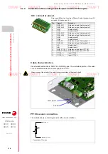
Page 97: ...ecure the cable to the connector General characteristics Type Shielded Twisted pair 1 x 2 x 0 22 mm with a characteristic impedance of 120 AWG 24 gage Flexibility Extremely flexible Minimum bending ra...

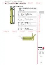
Page 98: ...connector for ribbon cable Maximum height of the connector 14 5 mm Connector I44A Connector I44B Pin Signal Description 1 GND 0 V reference signal 2 24V_OUT 24 V output for digital inputs 3 26 I1 I24...

Page 99: ...ale Phoenix Contact minicombicon 3 5 mm pitch Pin Signal Function 1 GND_AO1 Reference signal Analog output 1 2 GND_AO2 Reference signal Analog output 2 3 AO1 Analog output 1 4 AO2 Analog output 2 5 GN...

Page 100: ...Remote modules RIO5 RIOW and RIOR series CNCelite 8058 8060 8065 8070 5 RIOR E 48I32O RIOR E 48I32O ANALOG CANOPEN Connection of the analog inputs outputs and the PT100 inputs 100 REF 2107...

Page 101: ...32O RIOR E 48I32O ANALOG ETHERCAT RIOR E modules are input output modules that connect to the CNC via the EtherCAT bus Module Type of inputs outputs RIOR E 48I32O 48 digital inputs 32 digital outputs...

Page 102: ...for elecrical equipement for measurement control and laboratory use Particular requirements for control equipment Canadian Standards Associations CSA C22 2 No 142 Process Control Equipement Packaging...

Page 103: ...voltage 12 bits 10 V if configured to current 12 bits 20 V 4 AO 16 bits 10 V 2 PT100 12 bits 200 to 850 C range 328 to 1562 F 0 1 C resolution Type Description Do not touch or handle exposed parts of...

Page 104: ...qualified personnel skilled in its use The equipement shall be supplied with the specified rated voltages according to the hardware manual The nature of the installation where it is connected must no...

Page 105: ...RIO5 RIOW and RIOR series CNCelite 8058 8060 8065 8070 RIOR E 48I32O RIOR E 48I32O ANALOG ETHERCAT Dimensions 105 REF 2107 6 2 Dimensions Db b a Da c mm inch Da 120 4 72 Db 256 10 08 mm inch a 150 5...

Page 106: ...s running 6 3 2 Cabinet design The enclosure must meet the following requirements Protection degree IP 54 minimun according to EN 60529 Protection degree IK 08 minimun according to IEC 62262 Enclosure...

Page 107: ...output voltage For all connections and terminals of electronic modules use only power supplies that provide SELV Safety Extra Low Voltage or PELV Protective Extra Low Voltage output voltages Power sup...

Page 108: ...protect it against voltage peaks The power supply must be connected to the ground shield of the module for functionality or electromagnetic compatibility for electromagnetic compatibility this connect...

Page 109: ...Connectors 109 REF 2107 6 5 Hardware functionality Connectors Connector A22 24 V DC supply input B64A B64B EtherCAT bus I44A I44B Digital inputs and outputs I48 PT100 analog inputs and outputs only fo...

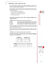
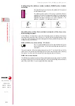
Page 110: ...inimum maximum section 0 2 2 5 mm Minimum maximum AWG section 24 12 Rated current In 12 A Cable data Length to be stripped 7 mm See 6 4 Power supply for the module on page 107 See 6 7 2 EtherCAT bus c...

Page 111: ...On Module in OPERATIONAL state RN Red LED Blinking rate Description Off No errors Intermittent Communication or configuration error On No communication ER 50 pin male IDC connector with a latch Use a...

Page 112: ...inputs outputs and the PT100 inputs on page 118 Plug in part 8x2 pin two level male Phoenix Contact minicombicon 3 5 mm pitch Rated current 8 A Pin Signal Function 1 GND_AO1 Reference signal Analog ou...

Page 113: ...the following characteristics Analog outputs Use shielded cables connecting the shields to the ground plate of the module itself All the analog outputs have the following characteristics Characterist...

Page 114: ...ics of the inputs and outputs 114 REF 2107 Inputs for the temperature sensors PT100 Use shielded cables connecting the shields to the ground plate of the module itself The electrical characteristics o...

Page 115: ...terminal 6 7 2 EtherCAT bus connection Use both B64 connectors to connect the module to the bus Insert the cable coming from the previous module into the IN connector and the cable going to the follo...

Page 116: ...nce the connection cable must be inserted all the way into the connectors so they re latched This ensures that the cable is properly latched and does not come off due to vibration ECAT CABLE cable Typ...

Page 117: ...a female connector for ribbon cable Maximum height of the connector 14 5 mm Connector I44A Connector I44B Pin Signal Description 1 GND 0 V reference signal 2 24V_OUT 24 V output for digital inputs 3...

Page 118: ...e Phoenix Contact minicombicon 3 5 mm pitch Rated current 8 A Pin Signal Function 1 GND_AO1 Reference signal Analog output 1 2 GND_AO2 Reference signal Analog output 2 3 AO1 Analog output 1 4 AO2 Anal...

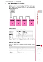
Page 119: ...or at both ends The connector has two shield pins Both pins are equivalent and the CAN shield may be connected to either one CAN cable characteristics Use a specific CAN cable The ends of all the wire...

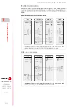
Page 120: ...CAN H SHIELD 4 0 F D C B 9 8 7 5 3 1 1 MODULE 2 0 ADDRESS 2 ISO GND CAN L SHIELD CAN H SHIELD Line Term 1 1 0 Line Term 1 4 0 F D C B 9 8 7 5 3 1 ADDRESS 0 ISO GND CAN L SHIELD CAN H SHIELD ISO GND CA...

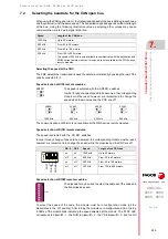
Page 121: ...r for any change at the Address switch to be assumed the CNC must be restarted and the corresponding drive must be reset however we recommend to change the address while the modules and the CNC are of...

Page 122: ...at one end of the line even when not having this switch The other end of the line will be the last physical device of the bus RIOW series remote modules TheRIOWseriesmodulesdonothaveafactory installe...

Page 123: ...select the speed of the node the module must be in configuration mode all the dipswitches in the off position After turning the module on in configuration mode the top 4 LED s of the module blink ind...

Page 124: ...e on position After saving the configuration the corresponding LED s turn on to indicate the module speed For 1 MHz all four LED s turn on Oncethespeedhasbeenselected turnthemoduleoffbyremovingpower a...

Page 125: ...Remote modules RIO5 RIOW and RIOR series CNCelite 8058 8060 8065 8070 125 User notes REF 2107...

Page 126: ...Remote modules RIO5 RIOW and RIOR series CNCelite 8058 8060 8065 8070 126 User notes REF 2107...

Page 127: ...Remote modules RIO5 RIOW and RIOR series CNCelite 8058 8060 8065 8070 127 User notes REF 2107...


Page 128: ...Fagor Automation S Coop B San Andr s 19 Apdo 144 E 20500 Arrasate Mondrag n Spain Tel 34 943 039 800 Fax 34 943 791 712 E mail info fagorautomation es www fagorautomation com FAGOR AUTOMATION...

Reviews: