2 System Overview
This section gives a brief overview of the FaderMate system in order to provide context for
sections 3
(Console Compatibility Requirements)
and 4
(Fitting Instructions)
.
More detailed descriptions of the roles of the various system components are given in the
Product Manual
http://fadermate.co.uk/downloads.html
2.1 Component Descriptions
A FaderMate system comprises two subsystem kits: a single
Master Control Unit (MCU)
kit
and up to 4
Fader Control Unit
(
FCU)
kits.
2.2 MCU Overview
The
Master Control Unit
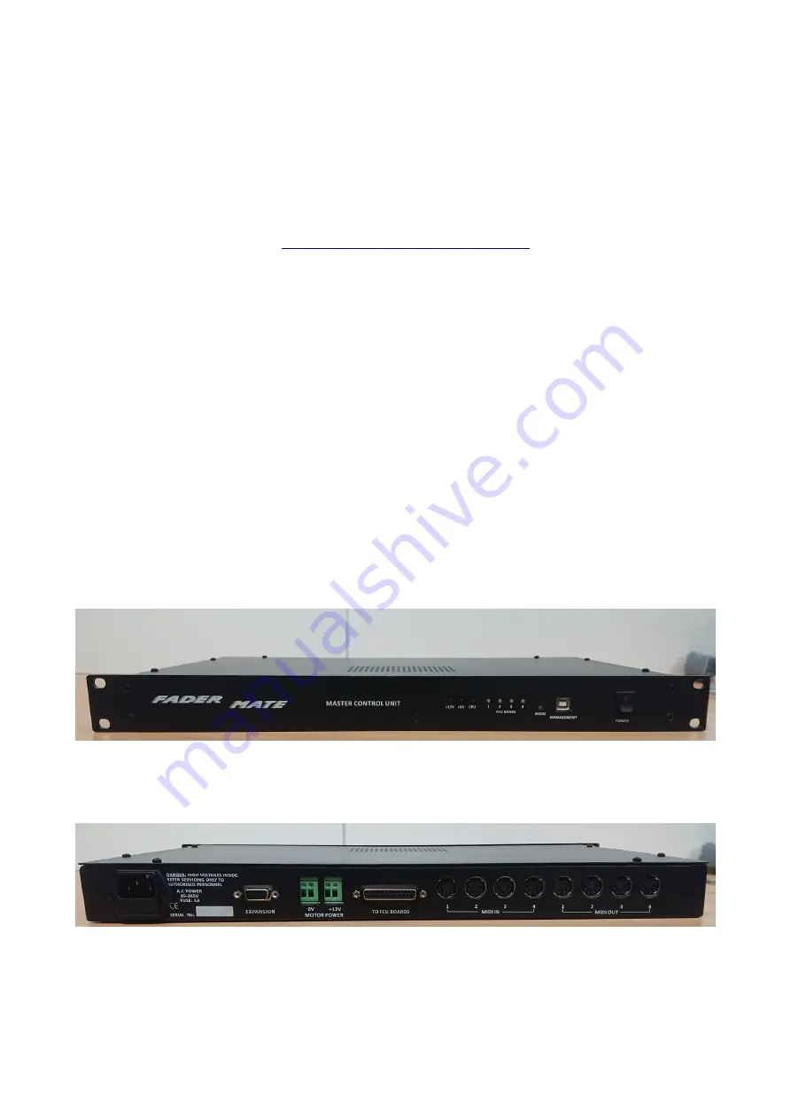
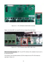
is the heart of the FaderMate system. It is a 1U rackmount
module which should be mounted close to the console. It connects the FaderMate system
to the computer by means of 8 MIDI DIN connectors (on the rear panel) and a USB
management connector (on the front panel).
The front and rear panels of the
MCU
are shown in Figures 2.2.1 and 2.2.2.
Figure 2.2.1 – MCU Front Panel
Figure 2.2.2 – MCU Rear Panel
4
Summary of Contents for Master Control Unit
Page 1: ...Product Fitting Guide v1 0 0 October 2018 2018 FaderMate All rights reserved 1...
Page 11: ...Figure 3 3 1 FCU Circuit Board Dimensions 11...
Page 23: ...Figure 4 4 4 Data Connections 23...
Page 26: ...Figure 4 5 4 Daisychain Power Connections Block Diagram 26...
Page 36: ...Version History Version Date Author Details 1 0 0 08 October 2018 AJN First release 36...


