


48
TTS-S-IM V2 09.22
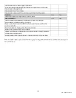
Final checklist
Review the following checklist. The answer to each of these questions should be “Yes”. If you answer “No” to
any of the items (except items with designated conditional answers), installation is not complete. Review the
appropriate sections to complete the installation. If you have any questions or need assistance with the
installation, contact Facilities Resource Group at 877-554-0004.
Before Installation
Yes
No
Rating Plate indicates the correct gas type (Natural Gas / Propane)
Water Heaters and frame are free of physical damage
Installation location is below 2,000 ft (610m)
If the answer above is no: Is dipswitch in each unit set to proper
altitude setting?
(Refer to the Water Heater Installation manual for instructions on
making this adjustment)
Mounting
Yes
No
For wall type, wall is capable of supporting shear load of the frame and
water heaters
Frame is mounted on a flat, level surface
Frame is securely fastened to the wall / floor as required by local building
code
Venting
Yes
No
Vent materials used are approved for use with these Category IV
appliances (PVC, CPVC, approved Polypropylene)
Vent length is within requirements
Clearance from termination meets the clearance requirements
While operating there is no leakage from any fitting or pipe
Vent system has a horizontal section
If the answer above is yes: Horizontal section has a slope of at
least ¼” upwards for each 12” toward the termination
Gas Supply
Yes
No
Gas inlet supply pressure is between 3.5-
10.5” w.c. (NG) or 8
-
14” w.c. (LP)
There is no leakage from water heater or gas connection
Gas pipe connection to gas manifold connection is appropriate
Unused end of the gas manifold is capped
Water Supply
Yes
No
Water supply pressure is between 15-150 psi (103.4-1034 kPa)
(Recommended water pressure between 30-70 psi (207
–
483 kPa) for
maximum performance. Installing a pressure regulating valve above 70
psi supply pressure can help to reduce water hammer)
There is no leakage from the cold water supply pipe, hot water supply
pipe, or the water heaters
Pressure relief valves are installed and piped in accordance with local
building code
Condensate Drain
Yes
No
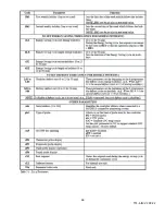
Summary of Contents for Standard Series
Page 4: ...4 TTS S IM V2 09 22...
Page 8: ...8 TTS S IM V2 09 22 View from Top 11 Slide the TTS rack forward to remove from crate 10 9 8 7...
Page 22: ...21 TTS S IM V2 09 22...
Page 26: ...25 TTS S IM V2 09 22 TTS S Specifications Parameters...
Page 35: ...34 TTS S IM V2 09 22...
Page 44: ...37 TTS S IM V2 09 22 Digital Controller Functions Overview...
Page 45: ...38 TTS S IM V2 09 22...
Page 46: ...39 TTS S IM V2 09 22...
Page 47: ...40 TTS S IM V2 09 22...
Page 48: ...41 TTS S IM V2 09 22...
Page 49: ...42 TTS S IM V2 09 22...
Page 50: ...43 TTS S IM V2 09 22...
Page 51: ...44 TTS S IM V2 09 22...
Page 52: ...45 TTS S IM V2 09 22...
Page 53: ...46 TTS S IM V2 09 22...
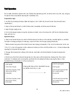
Page 54: ...47 TTS S IM V2 09 22 Timer Switch Operation...
Page 60: ...53 TTS S IM V2 09 22...
Page 61: ...54 TTS S IM V2 09 22...