background image

41

10. Technical data

10.1 Operating conditions

Supply voltage

1 x 115 V, + 10 %/- 10 %, 60 Hz.

Motor protection

The pump requires no external motor protection.

Enclosure class

Indoor use only, IP42.
CSA enclosure type 2.

Insulation class

F.

Relative humidity

Maximum 95 %.

Maximum outlet pressure

150 psi (10.34 bar).

Inlet pressure

Sound pressure level

43 dB (A).

Ambient temperature

32 °F (0 °C) to 104 °F (40 °C).

Liquid temperature

36 °F (2 °C) to 230 °F (110 °C).
To avoid condensation in the control box and 

stator, the liquid temperature must always be 

higher than the ambient temperature.

Glycol

Maximum glycol concentrations with clean 

water:

50 % glycol @ 36 °F (2 °C).
Hydraulic performance change can be expected.

Watt readings

Accuracy: ± 1 watt.

Flow indicator

Provides a relative indication of flow – should 

not be used in lieu of a flow meter.

Check valve

Use of a check valve may reduce pump 

hydraulic performance (up to - 10 %).
Use a check valve in parallel pumping 

applications.

Curve conditions

Test liquid: Airless water.
Curves apply to a density of 983.2 kg/m

3

 and a 

liquid temperature of 140 °F (60 °C).
All curves show average values and should not 

be used as guarantee curves. If a specific 

minimum performance is required, individual 

measurements must be made.
Curves apply to a kinematic viscosity of 0.474 

cSt.

Approximate power usage

Liquid

temperature

Minimum

inlet pressure

167 °F (75 °C)

0.75 psi (0.05 bar)

194 °F (90 °C)

4.06 psi (0.28 bar)

230 °F (110 °C)

15.7 psi (1.08 bar)

Ambient 

temperature

[°F (°C)]

Liquid temperature 

Minimum

[°F (°C)]

Maximum

[°F (°C)]

32 °F

(0 °C)

36 °F

(2 °C)

230 °F

(110 °C)

50 °F

(10 °C)

50 °F

(10 °C)

230 °F

(110 °C)

68 °F

(20 °C)

68 °F

(20 °C)

230 °F

(110 °C)

86 °F

(30 °C)

86 °F

(30 °C)

230 °F

(110 °C)

95 °F

(35 °C)

95 °F

(35 °C)

194 °F

(90 °C)

104 °F

(40 °C)

104 °F

(40 °C)

158 °F

(70 °C)

In domestic hot water systems, keep 

the liquid temperature below 149 °F 

(65 °C) to eliminate the risk of lime 

precipitation.

Speed 

setting

Minimum Maximum

High

constant 

speed

III

39 W

45 W

Medium 

constant 

speed

II

15 W

30 W

Low

constant 

speed

I

5 W

8 W

Constant 

pressure

8 W

45 W

Constant 

pressure

14 W

45 W

Constant 

pressure

22 W

45 W

AUTO

ADAPT

5 W

45 W

Summary of Contents for Standard Series

Page 1: ...1 TTS S IM V2 09 22 TTS Total Tankless Solution Commercial Water Heating System Standard Series Installation Manual TTS S6 6 Water Heater System...

Page 2: ...nsions 23 TTS S Specifications Parameters 25 Securing Floor Standing TTS S Models 26 Freeze Prevention Insulation 27 Piping Connection Orientation 5 Total 27 Condensate Drain to Floor or with Pump 28...

Page 3: ...er Outlet Cold Water Inlet Gas Condensate Drain Building recirculation Reduction in labor hours Worry free installation Designed to fit through 3 0 x 7 0 Door Pre engineered system Pre configured cont...

Page 4: ...4 TTS S IM V2 09 22...

Page 5: ...s Refer to the following diagram for accessibility options for moving the rack system Orientation Pallet Jack Forklift Front Back Accessible Accessible Sides Not Accessible Accessible Note Before unpa...

Page 6: ...6 TTS S IM V2 09 22 TTS S2MINI 3 Side View TTS S4MINI 5 Side View TTS S6 Side View Unpacking the TTS Rack...

Page 7: ...r 4 screws to remove the left top retaining blocks 5 Remove one 1 screw from the top of the left side panel 6 Remove one 1 screw from the top of the right side panel View from Top 7 Remove two 2 screw...

Page 8: ...8 TTS S IM V2 09 22 View from Top 11 Slide the TTS rack forward to remove from crate 10 9 8 7...

Page 9: ...Q FF US NRCR111DV GQ C3260WXQ FF US NCC199CDV GQ C3260WZ FF US Noritz is dedicated to providing solutions that make installing our tankless water heaters as easy and flexible as possible A summary of...

Page 10: ...eturn line to the system from either a recirculation pump or a storage tank schedule 40 80 CPVC or PP must be used This water heater must be vented with plastic pipe materials as specified in the tabl...

Page 11: ...Manual or contact Noritz technical support 866 766 7489 How to tighten the vent pipe to the water heater 1 Continue to insert the Vent Pipe until it touches the base of the Water Heater Exhuast or Int...

Page 12: ...meter Material Noritz PVT HL 3 PVC Noritz PVC 2CT 2 PVC Noritz PVC 3CT 3 PVC Noritz PVC UCVK 2 or 3 PVC Noritz PVC 2LPT 2 PVC Noritz PVC 3LPT 3 PVC IPEX 196984 2 PVC IPEX 196985 3 PVC IPEX 196256 2 or...

Page 13: ...aximum 4 in 100 mm apart with the next pair maintaining a minimum of 24 in 0 6 m spacing from the next pair Refer to the Vent Termination Installation Manual for full clearance requirements Illustrati...

Page 14: ...the PVC 2LPT PVC 3LPT or PVC UCVK Multiple concentric terminations must be a minimum of 12 0 3m between terminations Do not vertically align multiple terminations Clearance Requirements Between Multi...

Page 15: ...sing 90 Elbows or Tee Fittings Maintain at least 3 ft 0 9m distance between the intake and exhaust of the appliance Maintain at least 1 ft 0 3m distance between the exhausts of multiple units When Usi...

Page 16: ...r terminations at un equal heights maintain 24 600 mm minimum clearance For terminations at equal heights maintain a 24 600 mm minimum clearance Note Drawings shown with optional PRC 1 accessory Commo...

Page 17: ...on Vent Installation For Canadian Installations only vent material approved to ULC S636 may be utilized When utilizing room air configurations a room air conversion kit SV CK 2 must be installed on ea...

Page 18: ...866 766 7489 Model Configuration No of Units Table 1 Vent Diameter in and Maximum Equivalent Vent Length ft PVC or CPVC Schedule 40 pipe PP Pipe 3 4 6 8 3 4 6 8 NCC199CDV GQ C3260WZ FF US Both Direct...

Page 19: ...t Length of Elbows TL shall be less than the values listed in the Table 1 above Count the number of elbows and multiply by the equivalent length of each elbow in accordance with Table 2 Termination fi...

Page 20: ...Requirements for Both Combustibles and Non Combustibles Indoor Outdoor with vent cap Top of Heater 12 300mm 36 900mm Left Side of Rack 3 75mm 3 75mm Right Side of Rack 3 75mm 3 75mm Front of Heater 4...

Page 21: ...Service and Maintenance when Common Venting When common venting the TTS system the following clearances are recommended in order to facilitate service and repair of the TTS system Inline Configuratio...

Page 22: ...21 TTS S IM V2 09 22...

Page 23: ...22 TTS S IM V2 09 22 The clearance requirements from vent terminations to building openings chart above apply to SV converted units TTS S Commercial Water Heating System Parts Number Main Components...

Page 24: ...3 Unit Total Tankless Solution Standard Series NG 599 700 BTU hr TTS S4MINI LP 4 Unit Total Tankless Solution Standard Series LP 799 600 BTU hr TTS S4MINI NG 4 Unit Total Tankless Solution Standard Se...

Page 25: ...S3 Total Tankless Solution Standard Series 599 700 BTU hr 52 25 31 5 80 TTS S4MINI Total Tankless Solution Standard Series 799 600 BTU hr 56 75 31 5 80 TTS S5 Total Tankless Solution Standard Series 9...

Page 26: ...25 TTS S IM V2 09 22 TTS S Specifications Parameters...

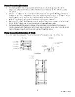
Page 27: ...r outlet side The pressure relief valve shall be operated once a year to ensure that it is functioning properly and there is no obstruction Turn the power off to the unit before opening the relief val...

Page 28: ...Heater Owner s Guide The built in freeze prevention on the water heaters require power to function When supplying combustion air from the indoors the room temperature must be greater than 32 F 0 C to...

Page 29: ...y piping to a floor drain Refer to NC 2 Installation Manual for full installation and usage instructions The end of the drain pipe must not be submerged in water or blocked in any way To ensure proper...

Page 30: ...container by pouring approx 10 oz 280ml of water into the exhaust accessory on the top of the appliance as illustrated below Or if the vent pipe has already been installed 2 After installing the drain...

Page 31: ...code sizing and installation guidelines Installation of Gas Supply 1 A licensed professional must install the gas supply 2 Turn off power supply 3 Turn off the gas and do not smoke or have other igni...

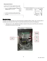
Page 32: ...factory These units are powered from the break panel located on the TTS Rack The Electrical Contractor will need to do the following Install one circuit 30A 208 240V 1Ph 3Wire w Ground to the panel o...

Page 33: ...ditional mounting instructions Only one remote controller is connected to the Noritz tankless water heater to monitor and control all the units If two or more remote controllers are connected a malfun...

Page 34: ...nace monitors and additional settings pg 16 The remote controller is not resistant to water steam chemcials or UV rays Store the remote in a location where it will not be exposed to these conditions M...

Page 35: ...34 TTS S IM V2 09 22...

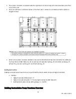
Page 36: ...it System Controller for additional multi system controller features such as warning and operation light pg 20 circulation pumps pg 21 exhaust fan pressure switch pg 22 and thermostat pg 23 Building R...

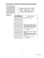
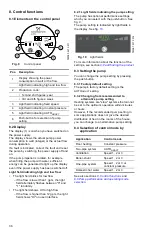
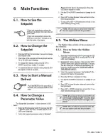
Page 37: ...f the settings see section 9 Fault finding the product 8 3 Setting the pump You can change the pump setting by pressing the push button 8 3 1 Factory default setting The pump s factory default setting...

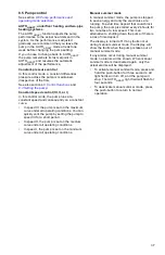
Page 38: ...s You can quickly vent the pump by setting the pump to speed III for a short period In speed II the pump is set on the medium curve under all operating conditions In speed I the pump is set on the min...

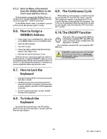
Page 39: ...rating conditions Constant pressure I The duty point of the pump will move left and right along the lowest constant pressure curve depending on the water demand in the system The head is kept constant...

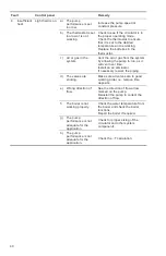
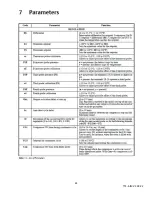
Page 40: ...oltage is too high Check that the power supply falls within the specified range b The rotor is blocked by impurities Remove the impurities ___ ___ a Supply voltage is too low Switch the power off and...

Page 41: ...nstall an air eliminator If necessary rework the piping d The valves are sticking Make sure all valves are in good working order i e remove lime deposits e Wrong direction of flow See the direction of...

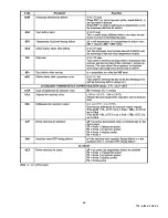
Page 42: ...mping applications Curve conditions Test liquid Airless water Curves apply to a density of 983 2 kg m3 and a liquid temperature of 140 F 60 C All curves show average values and should not be used as g...

Page 43: ...product or parts of it must be disposed of in an environmentally sound way 1 Use the public or private waste collection service 2 If this is not possible contact the nearest Grundfos company or servi...

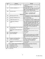
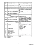
Page 44: ...37 TTS S IM V2 09 22 Digital Controller Functions Overview...

Page 45: ...38 TTS S IM V2 09 22...

Page 46: ...39 TTS S IM V2 09 22...

Page 47: ...40 TTS S IM V2 09 22...

Page 48: ...41 TTS S IM V2 09 22...

Page 49: ...42 TTS S IM V2 09 22...

Page 50: ...43 TTS S IM V2 09 22...

Page 51: ...44 TTS S IM V2 09 22...

Page 52: ...45 TTS S IM V2 09 22...

Page 53: ...46 TTS S IM V2 09 22...

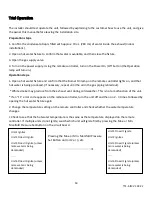
Page 54: ...47 TTS S IM V2 09 22 Timer Switch Operation...

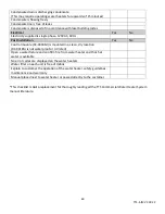
Page 55: ...uired by local building code Venting Yes No Vent materials used are approved for use with these Category IV appliances PVC CPVC approved Polypropylene Vent length is within requirements Clearance from...

Page 56: ...module RC 9018M is mounted in a clean dry location RC 9018M is not waterproof or UV rated Open a water fixture and confirm fire from water heater and that hot water is available No error codes are di...

Page 57: ...ut White smoke may produce from the exhaust vent during cold weather This is not a malfunction of the unit If an 11 error code appears on the remote controller turn the unit off and then on 2 3 times...

Page 58: ...rial operation clean the filter in the cold water inlet Use the remote controller to see the status of how many units are igniting Shutdown Steps 1 Stop any water demand 2 Turn off electrical power 3...

Page 59: ...TS System Components Warranty Registration Required Start Up Sheet Required Warranty Period Period of Coverage Date of Installation or 30 Days After Purchase Labor Parts Heat Exchanger Tankless Water...

Page 60: ...53 TTS S IM V2 09 22...

Page 61: ...54 TTS S IM V2 09 22...

Reviews: