


JP
1
5
15
正しくお取り扱いいただくために
•
この取扱説明書は器具の複数のレンジフードに適用されます。した
がいまして、特定の器具に適さない個々の特徴が説明されていると
ころもあります。
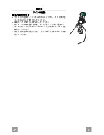
取り付けのしかた
•
メーカーは間違ったあるいは不適切な取り付けに起因する損傷につ
いては一切責任を負いません。
•
ガス器具とレンジフードの間の最低離隔距離は800mmです。
•
主要電圧がレンジフード内側の表示プレートに示されている電圧に
対応することを確かめてください。
•
この電気器具はアースを使用して適切に接地されなければなりませ
ん。
•
120mm
以上の直径を持つダクト配管を使ってレンジフードをダクト接
続口に接続してください。ダクト配管はできるだけ短くしてくださ
い。
•
レンジフードを(ボイラー、暖炉などの)燃焼の結果生じる煙を運
ぶ排気ダクトと接続しないでください。
•
レンジフードが非電気器具(たとえばガス燃焼器具)と同じ室内で
使用される場合は、室内の十分な換気がなされるようにしてくださ
い。きれいな空気がはいるようにするために、台所には外気に直接
に通じる通気口が必要です。
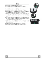
使用のしかた
•
このレンジフードは家庭使用のみを目的に台所の煙やにおいを除去
するために設計されました。
•
上記の目的以外の目的にはレンジフードを使用しないでください。
•
レンジフードが作動しているときには、フードの下に裸火炎を放置
しないでください。
•
火が鍋の横に出ないで下に当たるように火の強さを加減してくださ
い。
•
油のはいった深いフライパンからは使用中に目をはなさないで下さ
い。油は熱しすぎると燃えることがあります。
•
レンジフードの下で炎の上がる調理をしないでください。火事の危
険があります。
•
この器具は、安全責任を持つ人によって監督や器具の使用指導がお
こなわれないもとでは使用しないでください。子供を含めて身体的
、感覚的、精神的能力が減少している人、または経験や知識のない
人には使用させないでください。
•
この器具のそばで子供を遊ばせないでください。
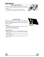
お手入れのしかた
•
お手入れの前には、電源スイッチを切るか、主要電源プラグを
抜
い
てください。
•
2
か
月
以内
毎
にフ
ィルタ
ーを
掃
除する
/交
換するようにしてください
。
•
レンジフードの
掃
除には
湿
った
布
と中
性洗剤
を使ってください。
Summary of Contents for Stilo Isola
Page 1: ...Stilo Isola...
Page 3: ...JP 3 3 15 16 18 22 23...
Page 5: ...EN 5 5 CHARACTERISTICS Dimensions...
Page 15: ...JP 1 5 15 120mm 2...
Page 16: ...JP 1 6 16...
Page 18: ...JP 1 8 18 21 20mm 10mm 11 7mm 10mm 2 4 5mm 20mm 12h 12g 22 23...
Page 19: ...JP 1 9 19 2 2 2 8 8 2 2 1 1 150mm 150mm 10 10 150 25...
Page 20: ...JP 2 0 20 6 7 Vx A B 8 C 9 A B 10 Vx A B C Vx...
Page 23: ...JP 2 3 23 LR03 AAA 1 5V FF 2 24h function E...
Page 24: ...JP 2 4 24 20 W 2 2 2...
Page 25: ...JP 2 5 25 Ca Lb Ca Lb...
Page 26: ......
Page 27: ......