Faber STILO DX/SP A90 Instruction Manual Download Page 4


EN 


4


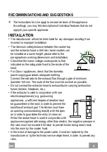
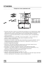
•  If the instructions for installation for the gas hob specify a greater distance 

specified above, this has to be taken into account. Regulations concerning 
the discharge of air have to be fulfilled. 

•  Use only screws and small parts in support of the hood.  

Warning

: Failure to install the screws or fixing device in accordance with 

these instructions may result in electrical hazards. 

•  Connect the hood to the mains through a two-pole switch having a contact 

gap of at least 3 mm. 

USE 

• 

The extractor hood has been designed exclusively for domestic use to 
eliminate kitchen smells. 

•  Never use the hood for purposes other than for which it has been designed. 
•  Never leave high naked flames under the hood when it is in operation. 
•  Adjust the flame intensity to direct it onto the bottom of the pan only, making 

sure that it does not engulf the sides. 

•  Deep fat fryers must be continuously monitored 

during use: overheated oil can burst into flames.  

•  Do not flambè under the range hood; risk of fire. 
•  This appliance can be used by children aged from 

8 years and above and persons with reduced 
physical, sensory or mental capabilities or lack of 
experience and knowledge if they have been given supervision or instruction 
concerning use of the appliance in a safe way and understand the hazards 
involved. Children shall not play with the appliance. Cleaning and user 
maintenance shall not be made by children without supervision. 


Summary of Contents for STILO DX/SP A90

Page 1: ...Instruction Manual...

Page 2: ...2 2 INDEX RECOMMENDATIONS AND SUGGESTIONS 3 CHARACTERISTICS 6 INSTALLATION 8 USE 11 MAINTENANCE 12 14 17 19 22 23 EN RU...

Page 3: ...ect the extractor to the exhaust flue through a pipe of minimum diameter 120 mm The route of the flue must be as short as possible Do not connect the extractor hood to exhaust ducts carrying combustio...

Page 4: ...poses other than for which it has been designed Never leave high naked flames under the hood when it is in operation Adjust the flame intensity to direct it onto the bottom of the pan only making sure...

Page 5: ...more frequently for particularly heavy usage Clean the hood using a damp cloth and a neutral liquid detergent The symbol on the product or on its packaging indicates that this product may not be trea...

Page 6: ...Section 2 2 1 Lower Section 8 1 Directional Air outlet Grille 125 mm 9 1 Reducer Flange 150 120 mm Ref Q ty Installation Components 7 2 1 2 Upper Chimney Section Fixing Bracket 11 7 Wall Plugs 12a 7 S...

Page 7: ...EN 7 7 Dimensions SX DX min 730 max 1000 min 730 max 1000 Min 500mm Min 650mm Min 500mm Min 650mm...

Page 8: ...indicated at X mm under the first bracket X upper chimney height aligning its central point on the vertical reference line Draw the central points of the bracket holes Draw the reference point as indi...

Page 9: ...the choice of which is left to the installer To install a 120 mm air exhaust connection insert the reducer flange 9 on the hood body outlet Fix the pipe in position using sufficient pipe clamps not s...

Page 10: ...assembly Upper exhaust Chimney Slightly widen the two sides of the upper chimney and hook them behind the brackets 7 2 1 making sure that they are well seated Secure the sides to the brackets using t...

Page 11: ...the Motor on at Speed one Turns the Motor off T2 Speed On Turns the Motor on at Speed two T3 Speed Fixed When pressed briefly turns the Motor on at Speed three L Light Turns the Lighting System on an...

Page 12: ...to bend them Allow them to dry before refitting When refitting the filters make sure that the handle is visible on the outside Activated charcoal filter Recirculation version REPLACING THE ACTIVATED C...

Page 13: ...ion mm ILCOS Code 28 E14 220 240 104 x 35 HSGSB C UB 28 220 240 E14 20 G4 12 33 x 9 HSG C UB 20 12 G4 35 GU10 230 51 x 50 7 HAGS 35 230 GU10 51 40 50 GU10 230 51 x 50 7 HAGS 35 230 GU10 51 20 20 GU4 1...

Page 14: ...RU 1 4 14 650 I 120 0 04 2...

Page 15: ...RU 1 5 15 3 8...

Page 16: ...RU 1 6 16 2 4...

Page 17: ...RU 1 7 17 1 1 2 1 2 1 1 2 2 1 8 1 125 mm 9 1 150 120 7 2 1 2 11 7 12a 7 4 2 x 44 4 12c 6 2 9 x 6 5 12e 2 2 9 x 9 5 13 1 1 2 1 2 2 2 12c 12a 7 2 1 11 11 12a 12e 8 9 1 11 12a...

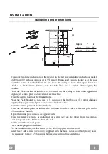
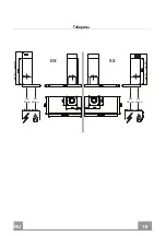
Page 18: ...RU 1 8 18 SX DX min 730 max 1000 min 730 max 1000 Min 500mm Min 650mm Min 500mm Min 650mm...

Page 19: ...RU 1 9 19 200 90 350 120 650 7 2 1 1 2 7 2 1 X X 116 970 Z Z 690 8 11 12a 4 2 x 44 4 2 12 4 2 x 44 4 5 6 Cappa Y Z 90 cm 200 565 120 cm 350 830 7 2 1 970 X 1 2 Y 116 650 min 116 Y 11 12a 690 Z...

Page 20: ...RU 2 0 20 2 Vr 12a 12 Vr 12 13 12a Vr 150 120 120 9 9 120 150 125 9 120 8 2 12e 2 9 x 9 5 9 125 8 12e...

Page 21: ...RU 2 1 21 3 7 2 1 4 12c 2 9 x 9 5 2 12c 2 9 x 9 5 2 1 2 2 7 2 1 12c 12c...

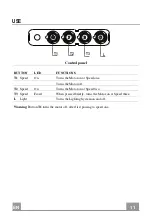
Page 22: ...RU 2 2 22 T2 T1 L T3 T1 T2 T3 L T1...

Page 23: ...RU 2 3 23 2 4...

Page 24: ...HAGS 35 230 GU10 51 40 50 GU10 230 51 x 50 7 HAGS 35 230 GU10 51 20 20 GU4 12 40 x 35 HRGS 20 12 GU4 35 30 20 GU5 3 12 46 x 51 HRGS 20 12 GU5 3 50 10 16 G13 95 720 x 26 FD 16 40 1B E G13 26 720 18 G1...

Page 25: ......

Page 26: ......

Page 27: ......

Page 28: ...436005061_ver3...

Reviews: