


12
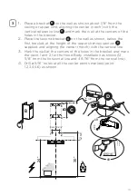
INSTALLING
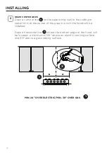
DRAW CENTER LINES
Draw a vertical line
X
on the supporting wall to the ceiling or
upper limit, at the center of the area in which the hood will be
installed.
Draw a horizontal line
Y
where the bottom edge of the hood will
be located, a minimum of 24" above an electric cooking surface
and 30" above a gas cooking surface.
2
MIN. 24" OVER ELECTRIC/MIN. 30" OVER GAS
Y
X
Y
Summary of Contents for STIL24SSV2
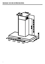
Page 6: ...6 RANGE HOOD DIMENSIONS DRAFT 27 AP 24 30 36 48...
Page 7: ...7 INSTALLATION HEIGHT REQUIREMENTS MIN 24 OVER ELECTRIC MIN 30 OVER GAS Min 24 Min 30...
Page 9: ...9 B A F C D E...
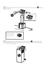
Page 16: ...16 8 Tighten the 2 screws H as shown H Phillips Screwdriver...
Page 17: ...17 CHOOSING VENTING METHOD VENTED RECIRCULATING Go to Pg 18 Go to Pg 22...
Page 30: ...30 WIRING DIAGRAM...
Page 36: ...36 DIMENSIONS DE LA HOTTE DRAFT 27 AP 24 30 36 48...
Page 39: ...39 B A F C D E...
Page 46: ...46 8 Serrez les 2 vis H comme illustr H Tournevis Phillips...
Page 47: ...47 CHOISIR LA M THODE D A RATION A RATION RECIRCULATION Allez la page 48 Allez la page 52...
Page 60: ...60 SCH MA DE C BLAGE...
Page 66: ...66 DIMENSIONES DE LA CAMPANA EXTRACTORA DRAFT 27 AP 24 30 36 48...
Page 69: ...69 B A F C D E...
Page 76: ...76 8 Apriete los 2 tornillos AL como se muestra AL Destornillador Phillips...
Page 90: ...90 DIAGRAMA DE CABLEADO...


