


4
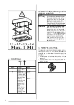
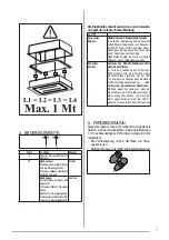
L1 = L2 = L3 = L4
Max. 1 Mt
L1
L2
L3
L4
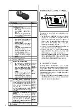
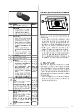
4. CONTROLS
Button
Function
Display
L
Turns the lights
On/Off.
-
T1
Hood Down
Press for 2 seconds
to raise the Hood.
Press briefly to turn
the Motor On/Off.
On/Off
Hood Up
Press once: The
Hood lowers.
Press a second
time: The Hood
Stops.
When the move-
ment has been
completed the
motor turns on at
Speed two.
Off/Off
The electronic control system recognises and
signals two types of fault
Led T1
Slow flashing
Current absorption threshold exceeded:
If an overload condition occurs, the fault
is signalled by LED
T1
on the keyboard
flashing once every 2 seconds. Check
that nothing is blocking normal hood mo-
vements.The signal remains active until a
new hood open/close command is given.
Rapid flashing
Hood opening safety microswitch tripped:
If the safety microswitch trips, the fault
is signalled by LED
T1
on the keyboard
flashing quickly (once every 250 ms). This
means that the hood has passed the mi-
croswitch……..
Call Technical Assistance!
You can continue to use the hood’s light
and motor functions while this fault is
active. Whenever the motor is on, LED T1
will continue to flash, indicating that the
fault is still present.
5. REMOTE CONTROL
The appliance can be controlled using a remote
control powered by a 1.5 V carbon-zinc alkaline
batteries of the standard LR03-AAA type (not
included).
• Do not place the remote control near to heat
sources.
• Used batteries must be disposed of in the
proper manner.
Summary of Contents for SKYLIFT X/WH F90
Page 36: ...36 1 650 I 120 0 04 3 2 3 W 4 Z 2 Z...
Page 37: ...37 L1 L2 L3 L4 Max 1 Mt L1 L2 L3 L4 4 L T1 2 T1 T1 2 T1 250 T1 5 1 5 LR03 AAA...
Page 48: ...48 1 650 I 120 0 04 3 2 3 W 4 Z 2 Z...
Page 49: ...49 L1 L2 L3 L4 Max 1 Mt L1 L2 L3 L4 4 L T1 2 2 T1 T1 2 T1 250 T1 5 LR03 AAA 1 5...
Page 50: ...50 2 2 2 24 10 10 24 30 2 24 24 10 24 2 1 B 2 3 6 1 EN60825 1 1994 A1 2002 A2 2001 439 7...
Page 72: ...72 1 650 mm I 120 mm 0 04 mBar 3 mm 2 3 W 4 Z 2 Z...
Page 78: ...78 1 650 mm I 120 mm 0 04 mbar 3 mm 2 3 W 4 Z 2 Z...
Page 79: ...79 L1 L2 L3 L4 Max 1 Mt L1 L2 L3 L4 4 L T1 2 Led T1 LED 1 2 LED 1 250 LED 1 5 1 5V LR03 AAA...
Page 81: ...81 1 650 1 120 0 04 3 2 3 W 4 Z 2 Z...
Page 82: ...82 L1 L2 L3 L4 Max 1 Mt L1 L2 L3 L4 4 L T1 2 T1 T1 2 T1 250 T1 5 LR03 AAA 1 5...
Page 83: ...83 2 2 24 10 10 24 30 0 5 24 2 24 10 24 2 1 B 2 3 6 EN60825 1 1M 1994 A1 2002 A2 2001 439 7 W...
Page 84: ...84 1 650 I 120 0 04 mbar 3 2 3 W 4 Z 2 Z...
Page 85: ...85 L1 L2 L3 L4 Max 1 Mt L1 L2 L3 L4 4 L T1 2 Led T1 LED T1 2 LED T1 250 LED T1 5 1 5 V LR03...
Page 90: ...90 1 650mm 1 120mm 0 04mbar 3 mm 2 3 W 4 Z 2 Z...
Page 93: ...93 65 I 120 04 0 4 2 W 65 I 120 04 0 4 2 1 2 3 Z...
Page 95: ...95 2 On Off 2 1 delay 24h 10 10 0 5 delay 24h 30 2 2 24H delay 24 10 24...
Page 97: ......
Page 98: ......
Page 99: ......
Page 100: ...991 0339 596_02 141117...


