


31
FOR INSTALLATIONS WITH LINERS
CUSTOM/WOOD
HOOD
STANDARD LINER
WARNING
!
When building a custom hood,
always follow all applicable
codes and standards.
1.
The custom/wood hood must have a sturdy base (3/4" plywood recommended) to
accomodate the cut-out for the Inca HC SS. The base must be recessed to accomodate
the height of the Liner (see
LINER DIMENSIONS
on Page 4). The Liner attaches to the
bottom of the base using screws appropriate for the size and material of your custom/
wood hood. The Inca HC SS inserts into the cut-out in the Liner and base.
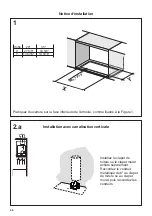
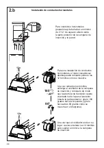
2.
Position the rear section of the Liner so that it abuts the back edge of your custom/
wood hood. Using a pen, trace the outline of the pre-cut out. Remove the Liner and
proceed to
MAKE YOUR CUT-OUTS
on Page 7. Install both sections of the Liner and
proceed to I
NSTALL THE Range hood
on Page 7.
INCA HC SS
The Inca HC SS can be used with
custom cabinetry and hoods 30"
wide and up. Choose either a
custom liner or our Standard Liner
designed for 30" and 36" wide
installations.
Liners create a perfectly-sealed,
non-combustible finish for the
underside of your custom/wood
hood.
The Standard Liners are made up of
two sections: a larger, rear section
(pre-cut out for insertion of the
Inca Smart) and a front section for
a total adjustable depth between
16" and 17
7/8"
.
!!! IMPORTANT NOTE:
YOU
MUST REMOVE THE ADDITIONAL
PERFORATED SECTION AROUND
THE PRE-CUT-OUT WHEN
INSTALLING THE STANDARD
LINER WITH THE INCA HC SS
MODEL.
Consider the shape, size, and
weight of the Inca HC SS and Liner
to determine the configuration
of the custom/wood hood. See
Range hood AND CUT-OUT
DIMENSIONS AND LINER
DIMENSIONS
on Page 4.
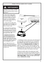
Lorsque vous construisez un habillage
de hotte sur mesure, assurez-vous de
toujours respecter les codes et normes
applicables.
AVERTISSEMENT
!
La hotte Inca SD peut être utilisée
avec des armoires et habillages sur
mesure d'une largeur de 30" et plus.
Vous pouvez choisir une caisse sur
mesure ou nos caisses standards
conçues pour occuper un espace de
30" ou de 36" de largeur.
Les caisses offrent une finition parfai
-
tement étanche et incombustible sur la
partie inférieure de votre habillage de
hotte sur mesure/ en bois.
Les caisses standards sont formées
de deux sections : une section arrière
plus large (précoupée pour l'insertion
de la hotte Inca Smart) et une section
avant, permettant de régler la profon-
deur (entre 16" et 17 7/8").
!!! REMARQUE IMPORTANTE :
VOUS DEVEZ ENLEVER LA SEC-
TION SUPPLÉMENTAIRE PER-
FORÉE AUTOUR DE LA SECTION
PRÉCOUPÉE LORSQUE VOUS INS-
TALLEZ UNE CAISSE STANDARD
AVEC LE MODÈLE Inca SD.
Tenez compte de la forme, de la
dimension et du poids de la hotte Inca
SD et de la caisse pour déterminer la
configuration de l'habillage de hotte sur
mesure/en bois.
1. L'habillage de hotte sur mesure/en bois doit présenter
une base solide (contre-plaqué de 3/4" recommandé)
pour permettre l'ouverture pour la hotte Inca SD. La
base doit être amincie pour accueillir la hauteur de la
caisse (consultez
DIMENSIONS DE LA CAISSE
à la
page 30). La caisse se fixe au bas de la base à l'aide
de vis adaptées à la dimension et au matériau de votre
habillage de hotte sur mesure/en bois. La hotte Inca SD
s'insère dans l'ouverture de la caisse et de la base.
2. Placez la section arrière de la caisse pour qu'elle
coïncide avec le bord arrière de l'habillage de hotte sur
mesure/en bois. À l'aide d'un stylo, tracez le contour de
l'ouverture précoupée. Retirez la caisse et
PRATIQUEZ
VOS OUVERTURES
. Installez les deux sections de la
caisse et
INSTALLEZ LA hotte
.
POUR L'INSTALLATION AVEC CAISSES
Summary of Contents for INCA SD Series
Page 6: ...6 Min 24 Min 30...
Page 17: ...17 Wiring Diagram 991 0530 011 H90 503 D00004494_00 120V 60Hz...
Page 23: ...23 Min 24 Min 30...
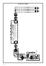
Page 34: ...34 Sch ma de c blage 991 0530 011 H90 503 D00004494_00 120V 60Hz...
Page 40: ...40 Min 24 Min 30...
Page 51: ...51 Diagrama de cableado 991 0530 011 H90 503 D00004494_00 120V 60Hz...
Page 53: ...53...
Page 54: ...54...
Page 55: ...55...


